Walser
Pistenraupen
Modellbau
Although the Jaegerndorfer PB 400 W is a ready to run model we modified and improved it. For example new tracks were made, and the lifting functions for the blade and tiller were optimized. We also added rotating beacons with a realistic rotating light effect and LEDs for the roof lights. A comprehensive test report of Klaus Bergdolt in the German magazine Truckmodell 3/2015 motivated us for this project.
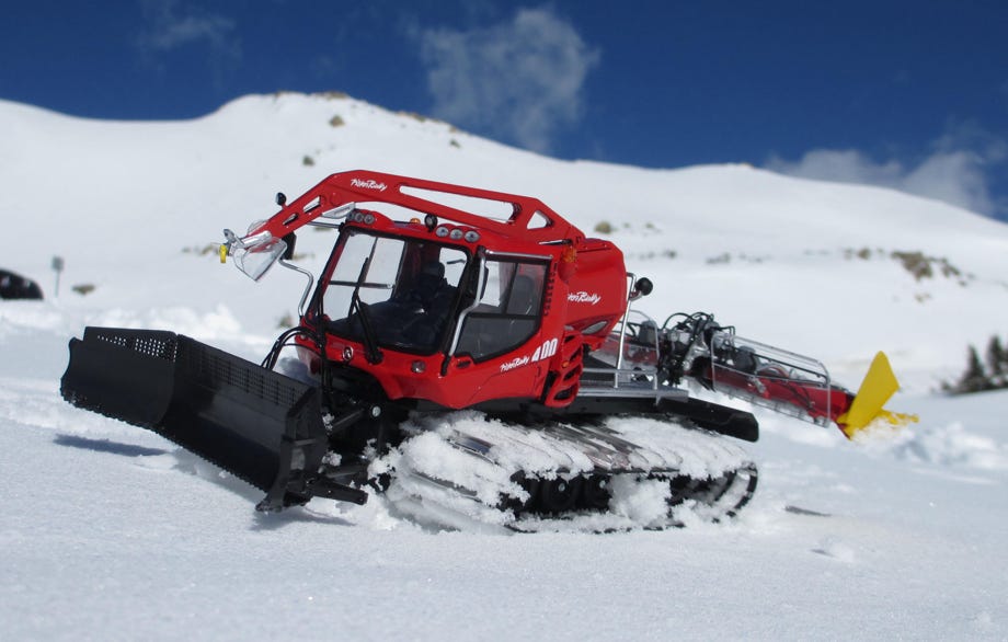
The JC PB400 W RC is a real beautiful model with fine details. It has a solid chassis which is a perfect base for own improvements. Here we describe our changes to the model in detail. A video clip of the first usage in real snow can be found on our video page.
The JC PB400 RC can be bought at the PistenBully Fan Store.
For the USA check out Jaegerndorfer-usa.com
Other dealers in different countries are listed on Jaegerndorfer's Webpage.
DISCLAIMER: An eventual warranty claim will get lost with some of the changes and modifications described below. All modifications are done at your own risk. WPM will not assume any liability whatsoever.
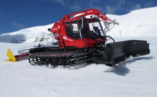
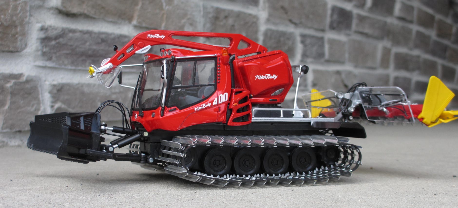
That's how the JC PB400 W presents itself directly out of the packaging:
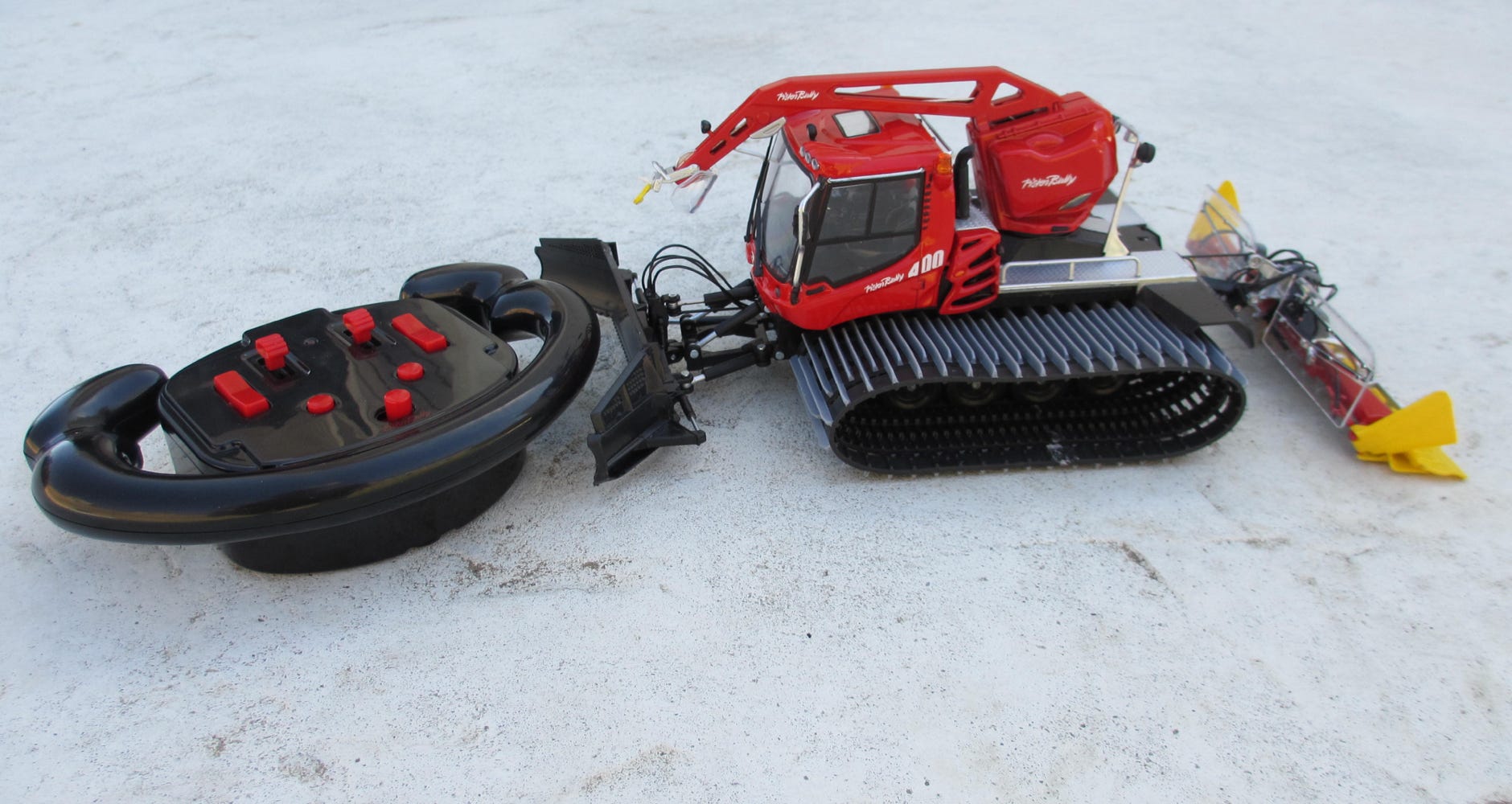
The appealing RC transmitter looks like a PistenBully steering wheel and offers proportional driving functions.
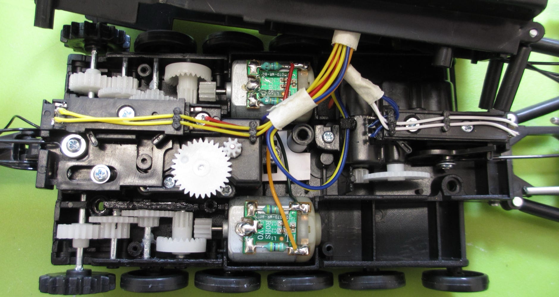
Solid gear box
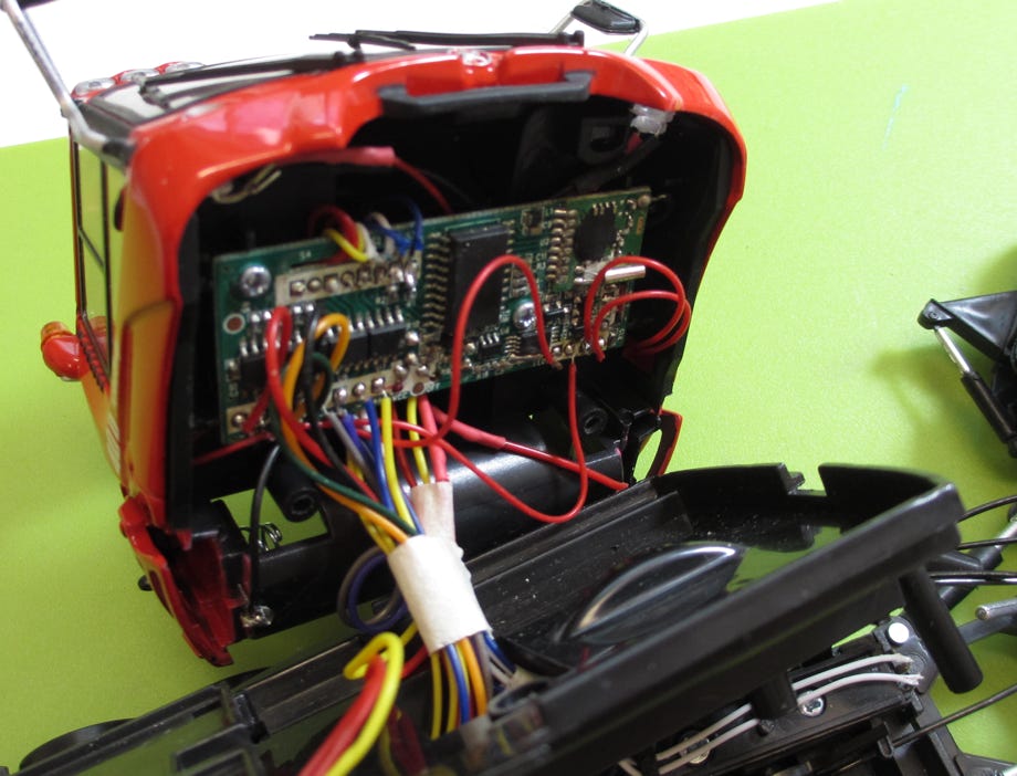
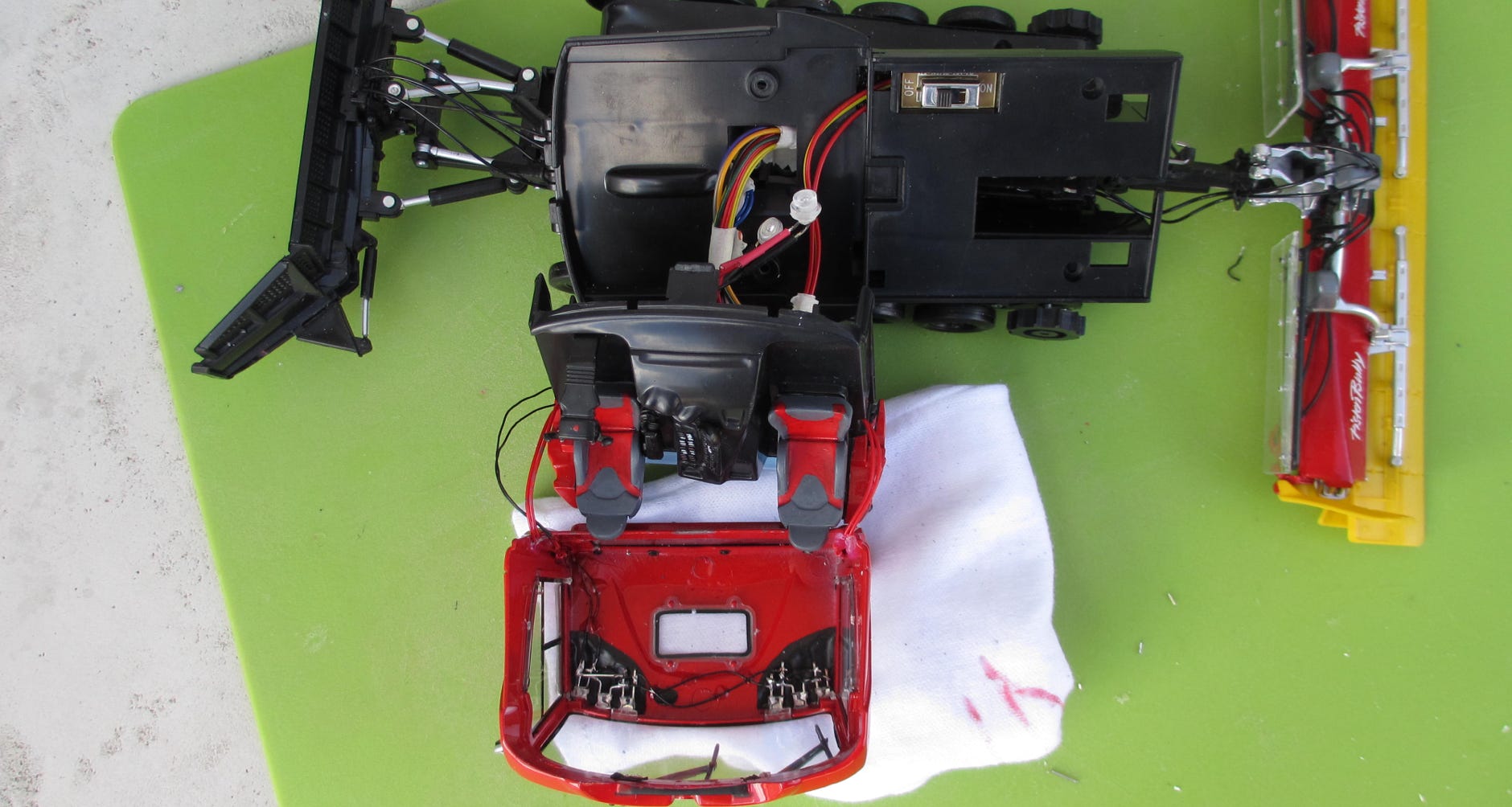
The electronics are underneath the drivers cabin
The Li-Ion 750 mAh battery is stored in the backpack
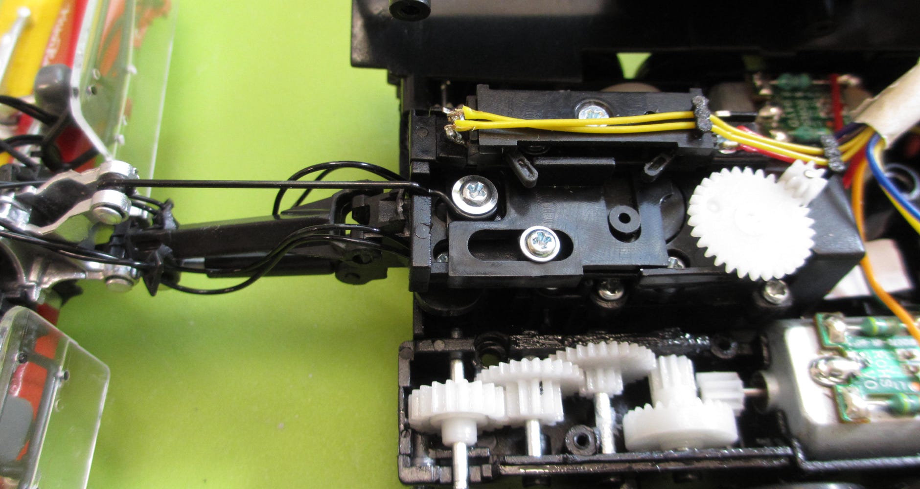
Lifting mechanism for the tiller. The end switches can be clearly seen.
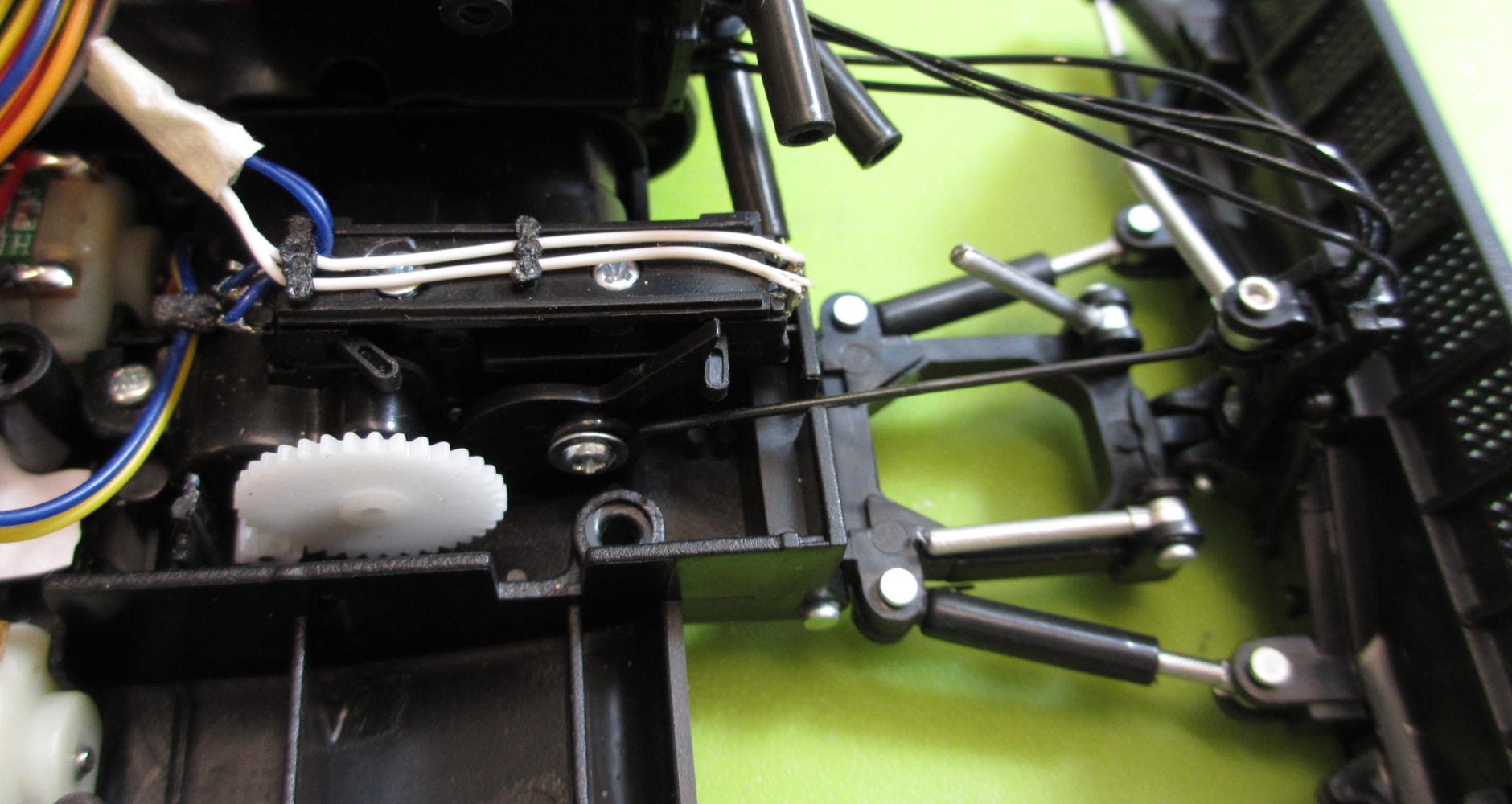
Lifting mechanism for the front blade. The end switches can be clearly seen.
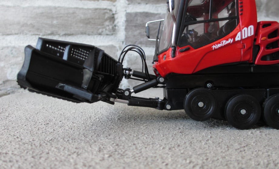
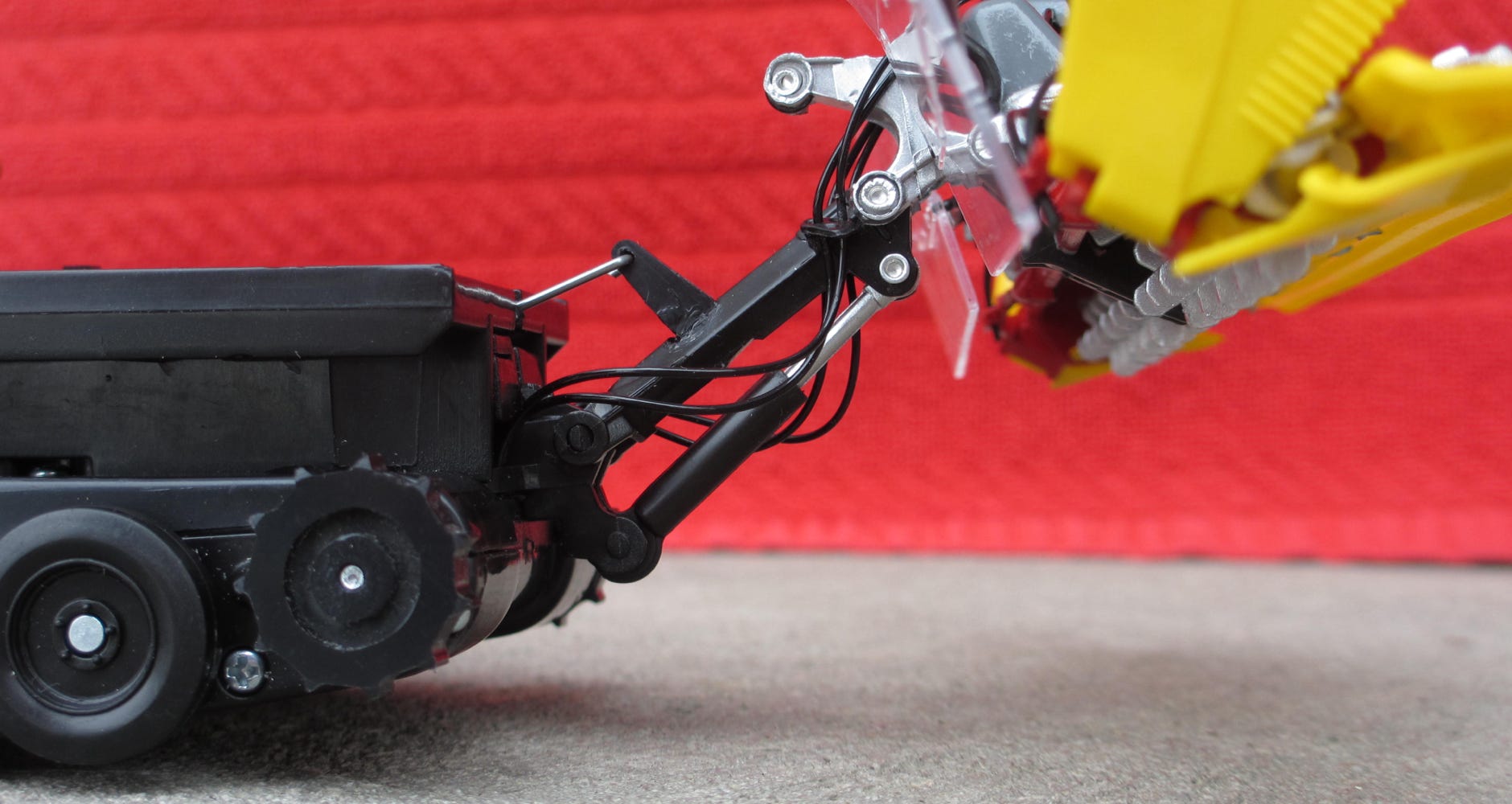
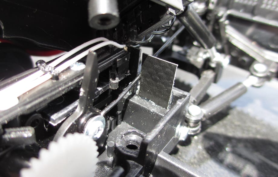
The steel wire pulls at the wrong joints at both auxiliaries: at the blade it is the joint of the cutting angle cylinder, and at the tiller it is the joint of the upper cylinder for the tiller angle. At the blade a sufficient height is reached, but at the tiller this is unfortunately not the case. The real lifting cylinder stays more or less in the same position, therefore the tiller is just tilted upwards. A little bit of height can be gained if the wire is bent a bit as seen in the picture below. To lift the tiller like the original, in any case a complete remake of the mechanism is necessary. But for now we will concentrate on the tracks, as the low lifting height is at least sufficient for driving backwards.
At the blade it is important to make sure that the whole mechanism moves easily. This was the case at our model, but Klaus Bergdolt claimed that at his model the lifting cylinders were tight. He also had to enlarge the forward joints of the swiveling cylinders so that they did not jam when lifting the blade.
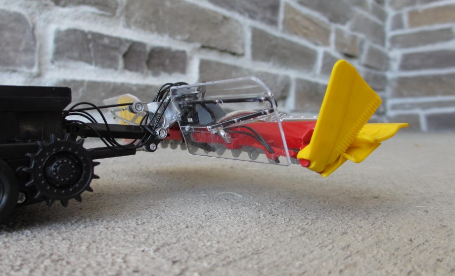
Maximum lifting height of the tiller.
Maximum lifting height of the blade
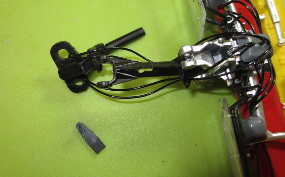
For testing purposes we moved the joint for the lifting wire with a clamp to the tiller arm, see video. The servo is strong enough to lift the tiller. This encouraged us to mill a slot into the tiller arm and glue a plastic lever into it. To this we connected a new, shorter steel wire. It's not really scale, though, but the original steel wire is neither. The joint has to be above the arm, otherwise the lifting will not work. After some investigations we chose a distance of 14 mm from the tiller arm joint and a height of 8 mm above the upper edge of the tiller arm.
We removed the tiller, for this task a couple of screws have to be removed. The tiller arm can be carefully levered out of the join with a flat screwdriver. But this is not absolutely necessary.
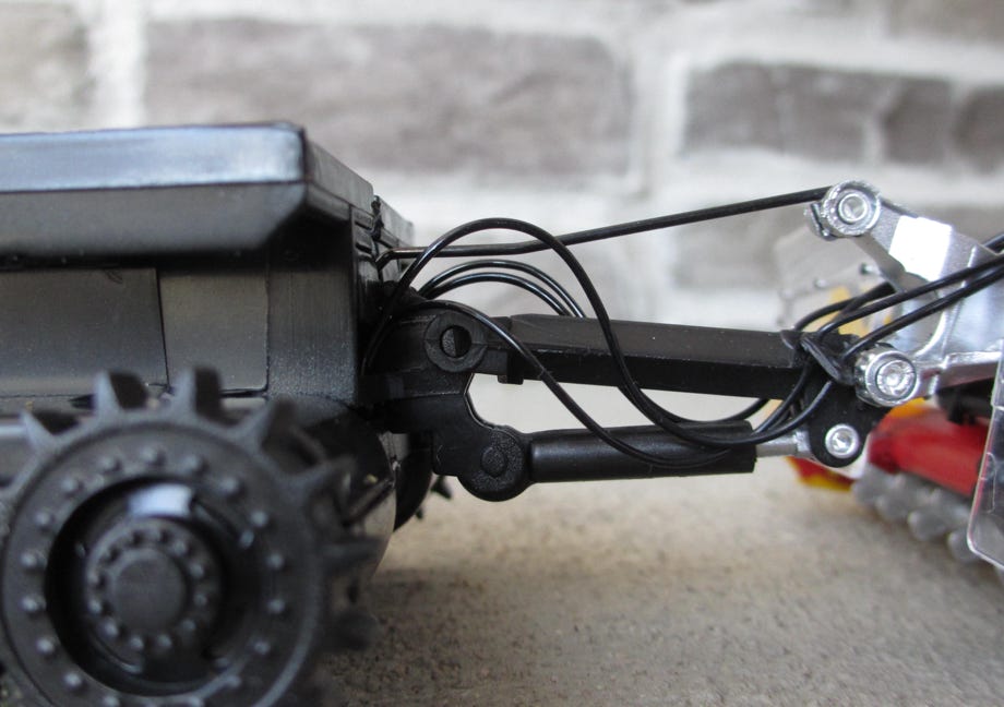
A small kink in the wire yields a few mm more height.
Milling of a slot into the tiller lifting arm
Slot and lever before glueing
Moving of the lifting joint of the tiller arm yields a considerable increase of the lifting height
The included rubber tracks are the same as those for the display model. They work, though, but a sensitive steering is rather not possible. They somewhat "wobble" around the wheels due to their stiffness instead of a smooth movement. Fortunately we could acquire one of the beautiful track kits by Kettenkraxler while they were still available. It is really impressive how precisely he bent these tiny parts. But Kettenkraxler is no longer making this kit, it’s way too much effort. Alternatively H0 rail road rails may be used for the cleats, which also looks good. You’ll find more to this in our article in Rad & Kette (see at the end under literature). You might need to use a translating tool because it’s in German.
Following our tradition also these tracks will get a name: Burmi-Tracks
Burmi (a marmot) is the kids mascot of our home Kleinwalsertal, and thus a fitting name for these small tracks.
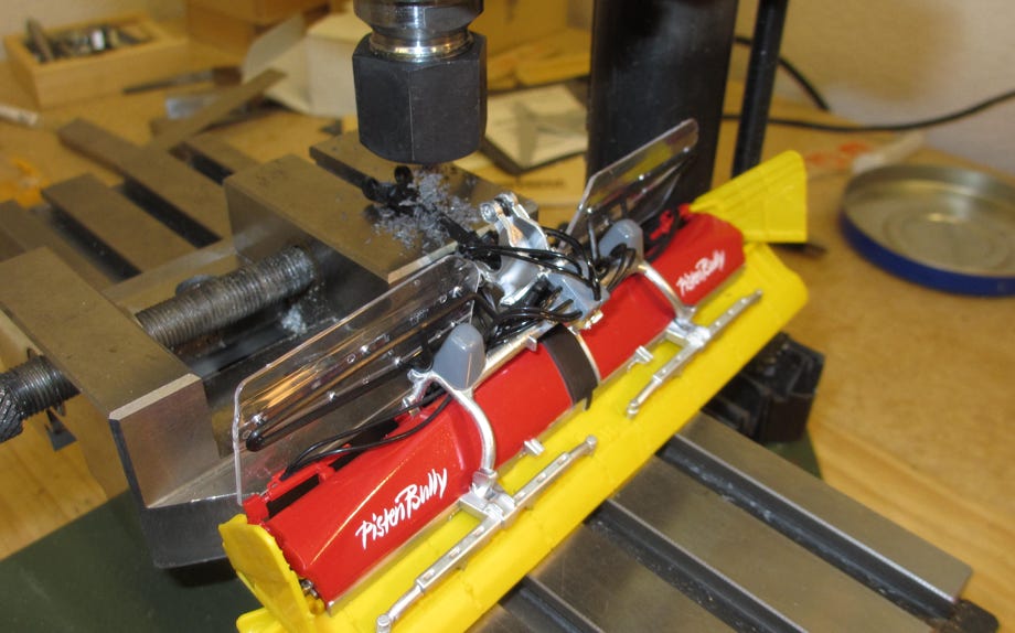
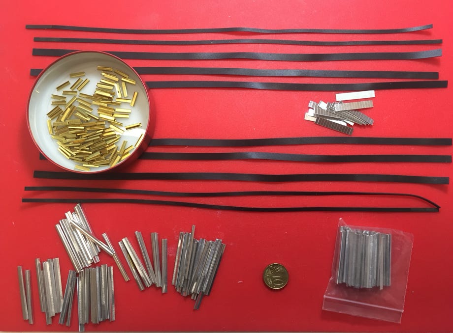
We used a template to chamfer the cleats: first all cleats were marked and then cut with small metal scissors. The kit includes brass profiles which have to be clamped around the cleats. The guide units can be soldered to these. This however seemed too much effort and therefore we decided to use guide units made from an aluminum U-profile. Our Stepcraft CNC milling machine with a Proxxon tool and a cutting blade was very useful for precisely cutting piece by piece of these tiny guide units.

Track kit by Kettenkraxler (no longer available)
Cutting the chamfers at the track cleats
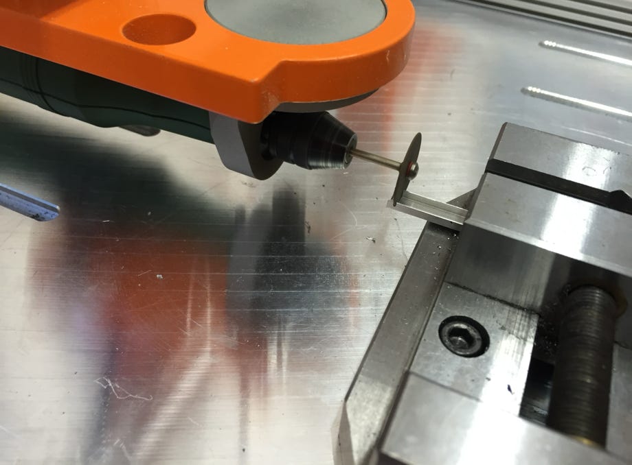
Mass production of guide units with the Stepcraft
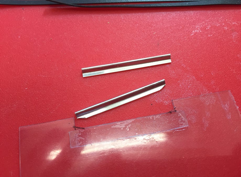
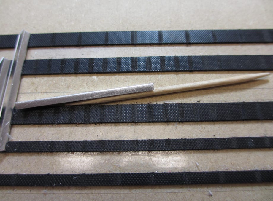
Track cleat and guide unit
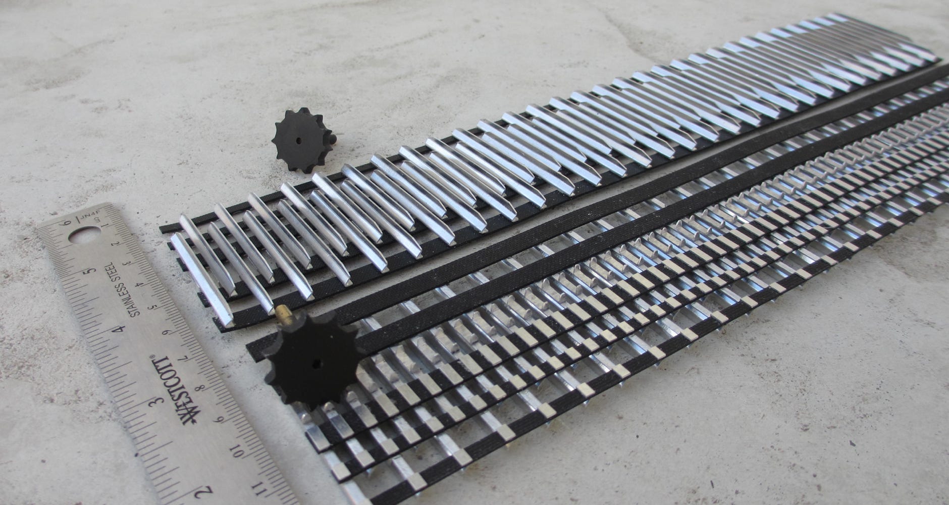
The tracks should fit rather tight, therefore we measured the track length around the wheels and sprocket with a ribbon. Our tracks have less cleats than the original tracks, therefore a new sprocket was necessary. The optimum solution was an 11 teeth sprocket. With 60 cleats a spacing of 4,62 mm was determined and a track length of 277,2 mm. The sprocket was CNC-milled out of black ABS plastic on our Stepcraft.
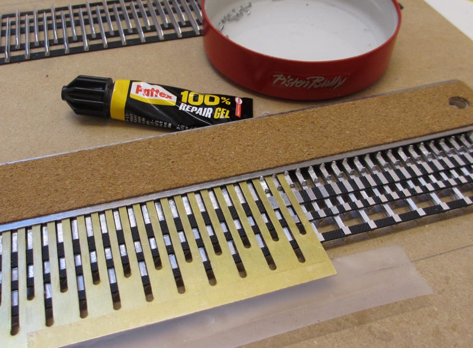
The rubber belts were fixed to a plate with double sided photo tape and aligned with a ruler. For precise positioning a brass template was milled, again on the Stepcraft. Prior to glueing the surfaces were roughened with 150 grain sanding paper. With the template this could also accurately be done on the rubber belts. After thoroughly degreasing the cleats were glued with Pattex 100% Repair Gel.
The template was sprayed with a dry lubricant to avoid glueing it by accident.
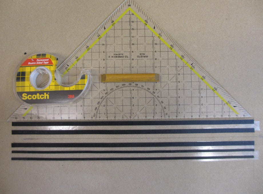
Precise aligning of the rubber belts
Sanding the surfaces for glueing
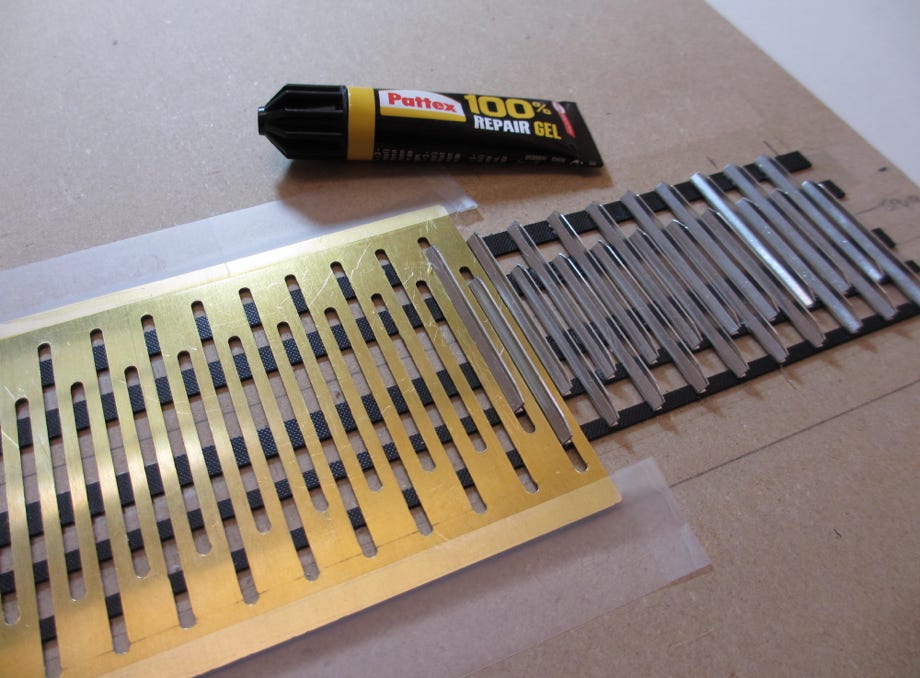
Template for precise positioning of the cleats
Glueing the guide units (with Loctite 435) and the counter plates (with Pattex 100% Repair Gel)
After finishing and deburring of the guide units they were glued to the cleats, again using the template. We are using the industry glue Loctite 435. We hope they'll stay on!
The counter plates were glued using Pattex 100% Repair Gel. Both inner belts have no counter plates, because they will not be visible with the JC chassis. Also the gap between the chassis box and the tracks is very small.
Finished tracks with the CNC-milled sprockets (first version made of aluminum)
The joining of the belts was done by using the template again. We glued the cutted ends of the belts directly to each other with Loctite 435. First the inner belts were glued, then we let them sit so they could bond. Then the outer belts were glued together. To be on the safe side we let the tracks rest overnight to make sure that the glue was thoroughly cured, before we mounted them to the PB400.
The shaft with the sprockets can be easily removed after opening of the gear box housing. The shaft is pressed into the sprocket. We drilled from the out side and pressed the shaft out. The shaft was then pressed into the new sprocket. First test runs showed that the sprockets need some modification, perhaps the teeth are a little bit to high.
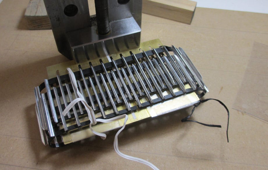
Glueing the belts together
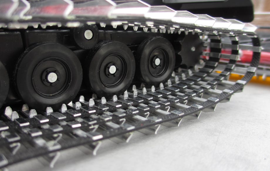
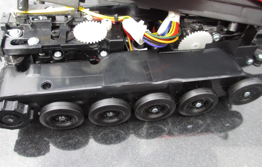
Installed tracks
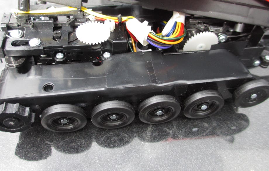
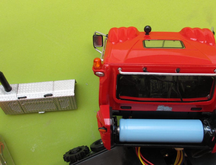
We subsequently removed the non original small guiding roll at the upper middle of the tub. We also grinded the cover a bit to avoid contact with the trace holders.
The JC PB400W RC with the new "Burmi tracks"
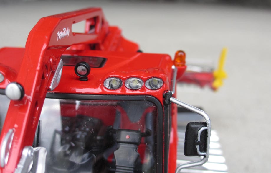
The originals work mainly at night, therefore good lights are a must. Unfortunately JC only fitted the model with LEDs fpr die lower parking lights, which are of no significance for the actual operation. Thus we added LEDs for the 6 head lights on the roof. We measured the voltage for the LEDs on the board with 2.7 V, and a subsequent test showed that the circuit can handle additional standard 3 mm LEDs.
To remove the cockpit, first the lower LEDs have to be pushed inwards, maybe with some force. The cockpit can be best removed by pressing the latch at the lower front inwards with a screw driver. Then we removed the glasses for the roof lights by cutting the fused caps at the inside with a knife. At the glasses we removed the pivot and sanded the inside plan with a small file until no silver color was visible any more. Then we drilled the holes carefully up to 3 mm by also using a protective fabric tape to avoid accidental damage to the body if slipping off with the drill. The LEDs were flattened, soldered in parallel and glued in position. As a safeguard against short circuits we attached pieces of black isolation tape at the roof.
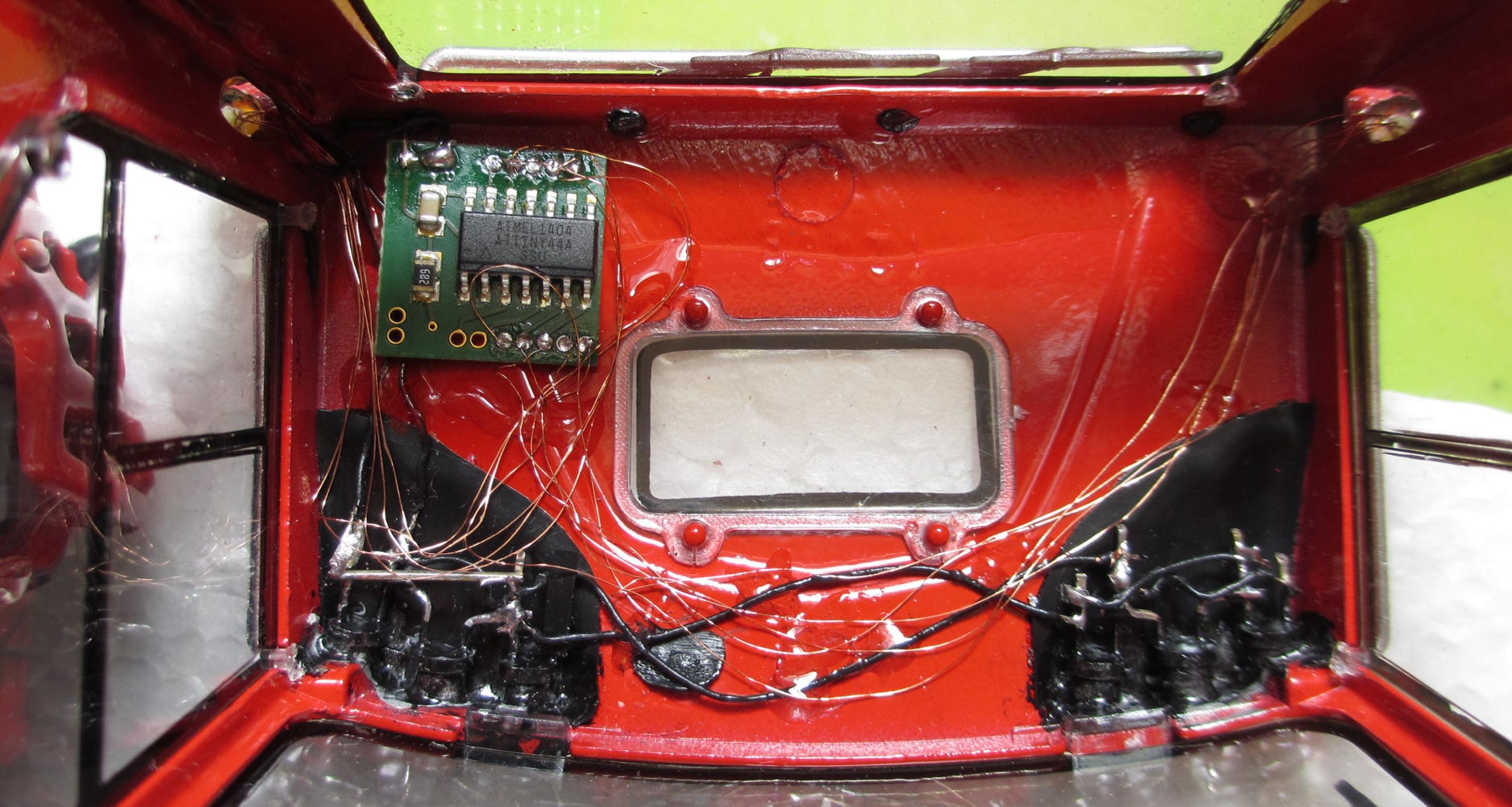
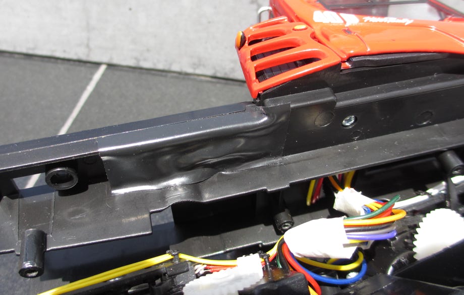
The connecting points for the additional head lights are marked on the picture. It is sufficient to only use two wires attached to two of the four connectors. Now the roof head lights can be switched on the remote control together with the parking lights.
Widening the holes to 3 mm
Protection against slipping off with the drill
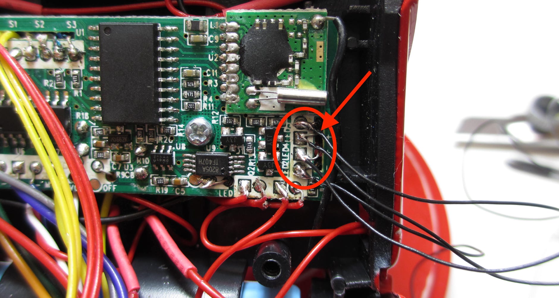
Contact points on the board for soldering the wires for the additional LEDs
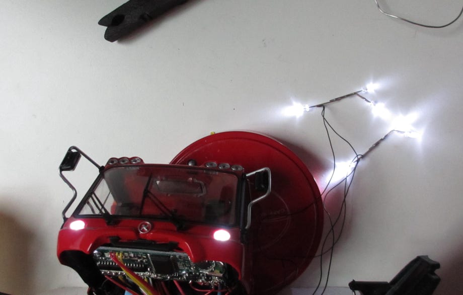
Test with 6 additional 3 mm LEDs
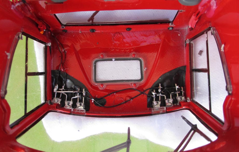
Installed LEDs for the roof head lights
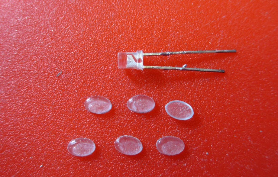
Flattened LED and head light glasses
Completed installation of LEDs and glasses
Finally the head light glasses were glued into place with a special clear hardening glue for plastic models.
Advice: The cables are unfortunately very stiff, and therefore some of them break easily at the soldering points with the unavoidable handling of the disassembled model. We repeatedly had to re-solder the broken cables. Especially when assembling the model we checked all functions after each step, and again had to remove the driver cabin to re-solder broken cables. The model is quite clearly not meant to be disassembled.
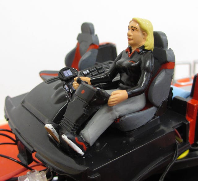
As we had the cockpit open we used this opportunity to paint the seats according to the original, and also added some color to the switches
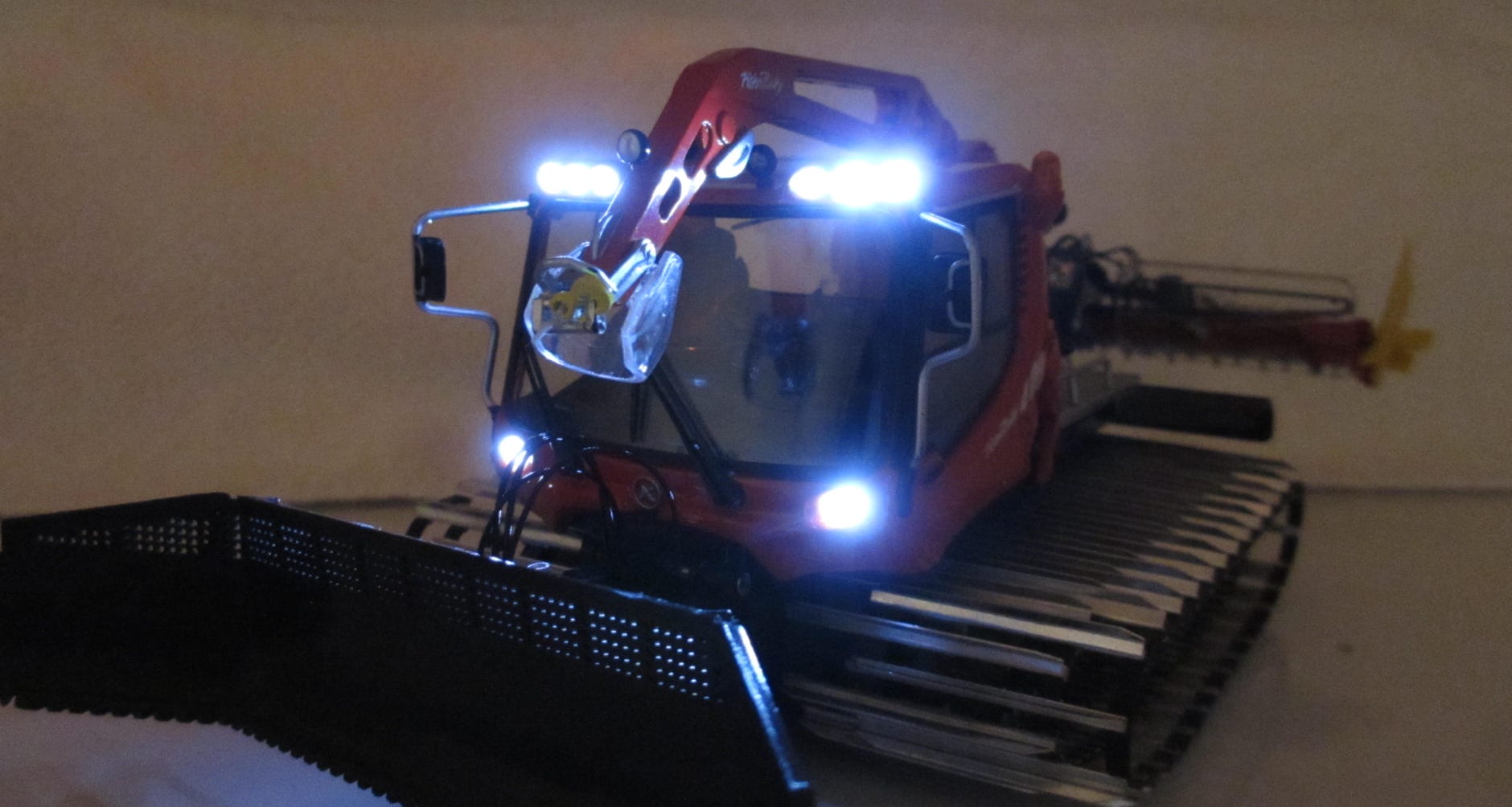
The PistenBully owns the night!
JC uses alternating flashing LEDs for the rotating beacons, which does of course not resemble the original at all. But this can be changed: Klaus Bergdolt made us aware of an electronic module by Taja-Elektronik, which is especially made for 1:32 models.
Meanwhile Fabio Cibolini discovered a cheaper and obviously better module by BEL, which can control up to 5 micro-LEDs.
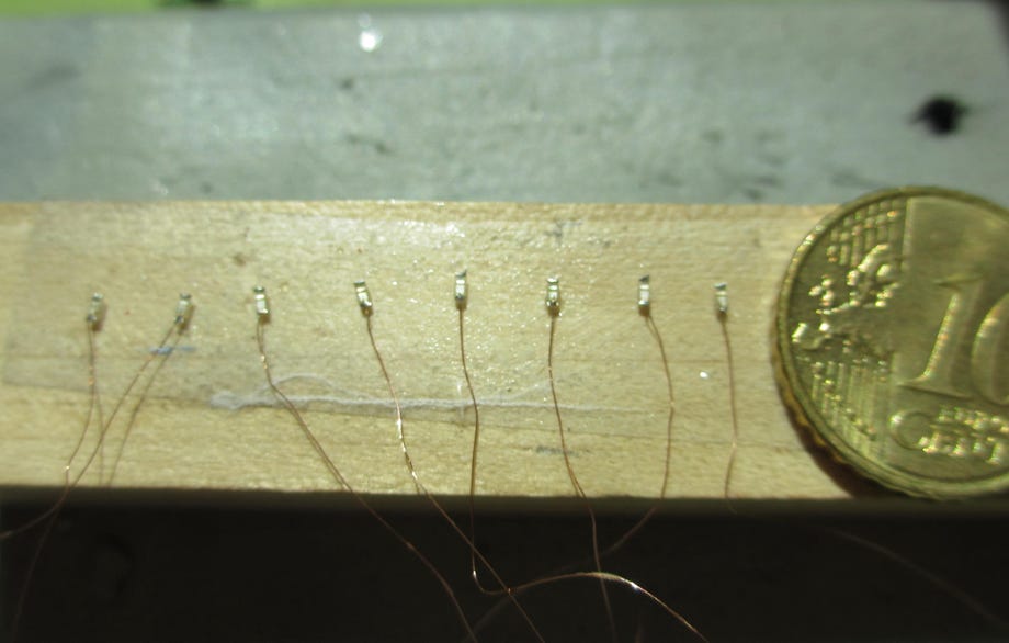
Taja-Elektronik also offers fitting micro-SMD-LEDs, of which we wisely ordered more than enough. If one of these tiny parts flies away from your work desk it is practically lost forever. After we bought a delicate 15W soldering iron we could start. The soldering is not as hard as it might first seem if you use a magnifier visor. One should also take care to only briefly touch the soldering point to avoid excessive heat transfer.
The micro-SMD-LEDs were hold in place by double sided tape for soldering the minus wire.
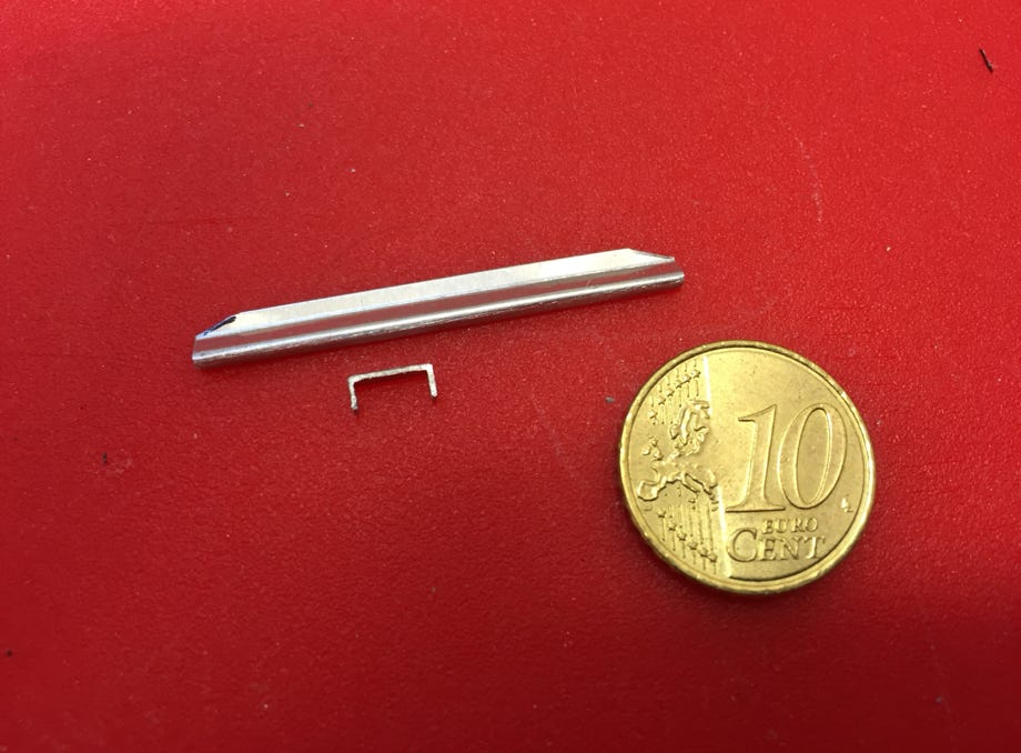
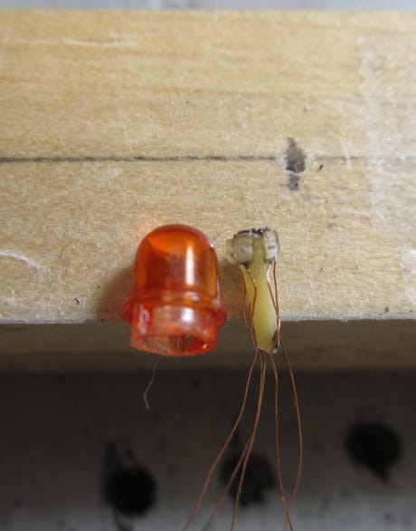
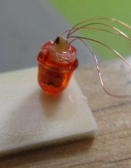
Rotating beacon cover and square rod with the micro-SMD-LEDs
According to the instructions in the blog of Taja-Elektronik we glued 4 SMD-LEDs with super glue onto a 0.9 x 0.9 mm square rod, which we made from an old circuit board. Wood may be used as well, for example from a round tooth pick. Then the plus wire was soldered to the top ends and everything tested.
The rotating beacon covers have been glued to the cabin and have to be carefully removed to avoid damage. The LED is also glued and after loosening it can be removed towards the top. The square rod with the SMD-LEDs is then glued to the beacon cover, and afterwards to the cabin. We used special crystal clear hardening glue for plastic models. Then the copper wires, which were previously marked in the correct order, are soldered to the board. The board itself is attached to the roof with some glue. The rotating direction of the beacon is clockwise when looked at it from the top.
We fixed the copper wires with drops of epoxy glue to the roof.
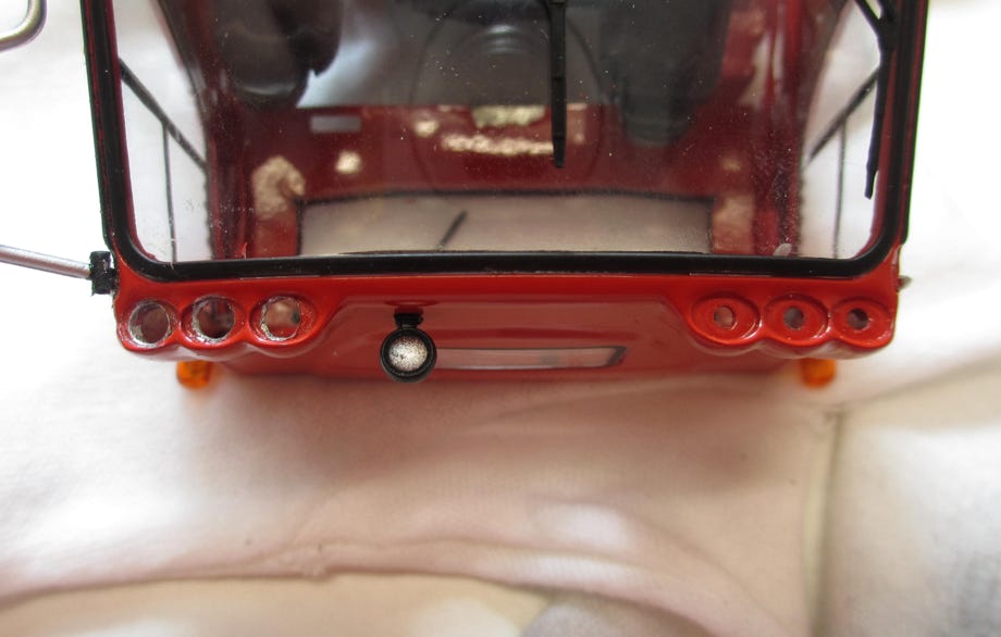
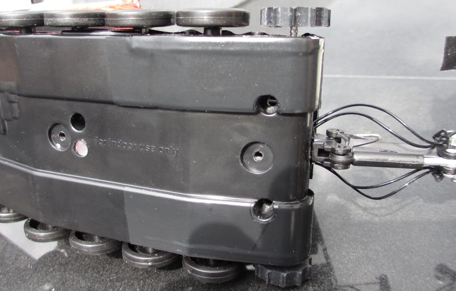
The manufacturer explicitly restricts the JC PB400 for indoor use only. Now wonder, as the chassis has more holes than Swiss cheese through which snow can get inside. To avoid unjustified warranty claims a moisture sensor is installed at the bottom of the tub.
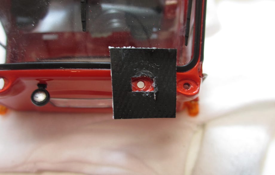
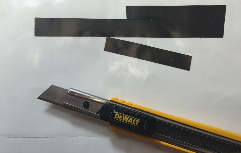
But to our opinion snow cats belong into snow, and therefore we thoroughly sealed the chassis. We are using high quality black electric insulation tape. It is important to seal all holes and gaps with tape, because intruding snow will melt to water. If the water gets in contact with the electronics an irreparable damage can happen quickly. All holes and gaps are clearly visible, and the pictures document how we did it.
Sealing of the gap at the blade lifting wire with rubber pads
Advice: The insulation tape can be easily cut in to smaller stripes by sticking it on the protective film of a sticker. Of course the sticker has to be removed beforehand. It does not really stick and can be removed like the sticker without loosing it's adhesive force.
Sealing of the opening below the on/off switch
Sealing of the upper side of the chassis
Sealing of the lower side of the chassis
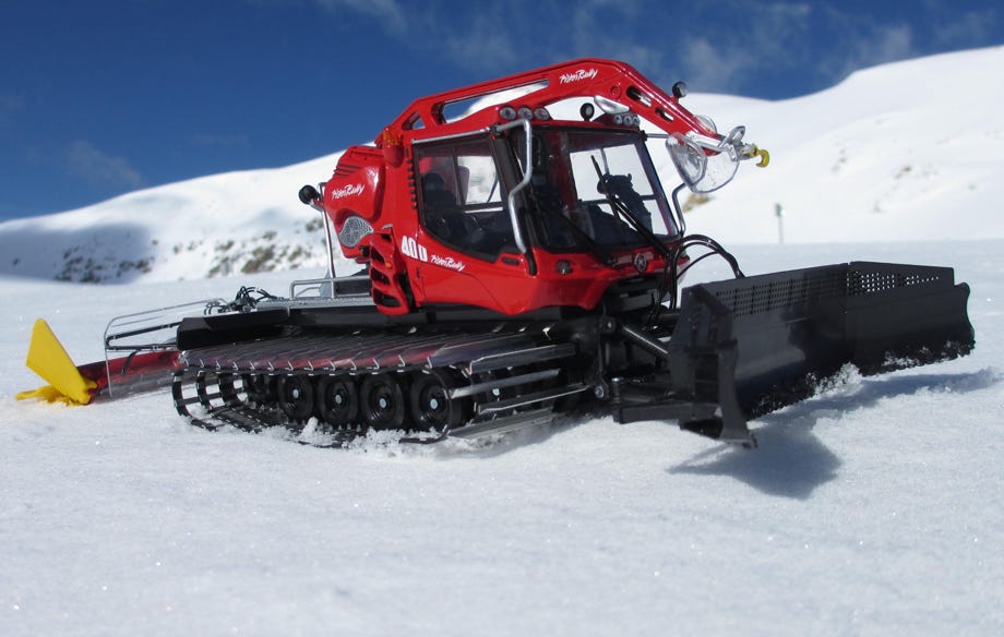
The first mission in snow was on May 20th, 2015 at Loveland Pass, Colorado at 3600m (11,800 ft) above sea level. The fresh snow provided nearly ideal conditions, although the snow quickly turned sticky in the morning sun and subsequently got stuck on the track claws.
Nevertheless the little model performed without problems and showed good driving characteristics with the new tracks. A short video of this first drive can be found on our video page.
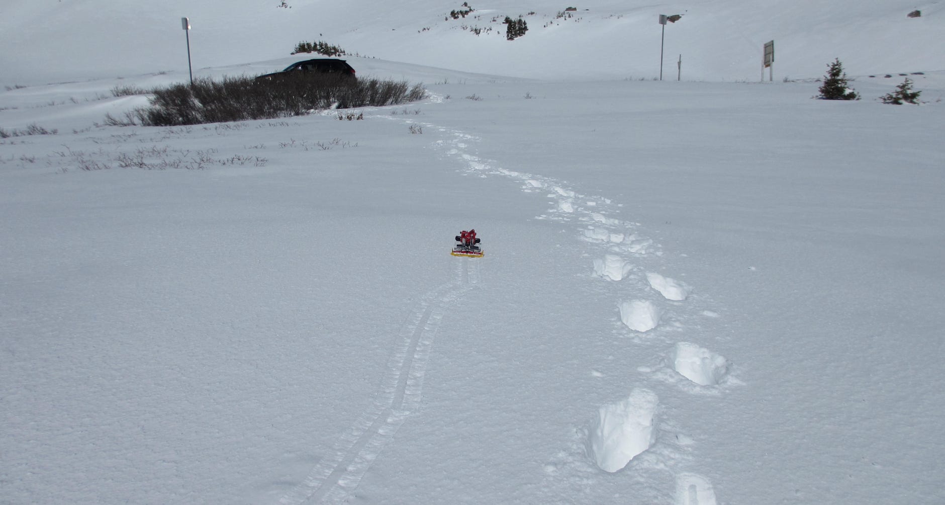
First mission in snow on May 20th, 2015 at Loveland Pass, Colorado at 3600m (11,800 ft) above sea level
A few tips for those who made it until down here ;-)
Tracks: The tracks were mounted wrong at both RC models we got. The left and right track were swapped. Please check if the tires are really running within the trace holders.
Rear View Mirrors: The mirrors have a protective foil which should be removed. If they are glued somewhat oblique, they may be easily removed with the tip of a knife and attached correctly. They have a self adhesive film on the backside.
Paint Repairs: Chrysler Engine Red No. 2732 of Testors Model Master paints matches the model's red almost exactly.
Wheel Axles: Finally we painted the silver tire axles black which considerably enhanced the appearance of the model, see picture to the left.
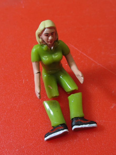
Driver Figures in 1:32 are available at Siku Models as accessories.
A few amputations were necessary to fit the Siku driver figure into the snow cat. In addition she was re-painted, and of course she is also wearing VANS Sk8-High shoes like all of our snow cat drivers.
JC PB400 W with black painted wheel axles
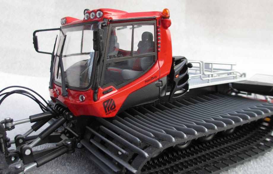
The PB400 can be re-painted to the ParkPro version with relatively low effort. This is described here in more detail.
The fitting decals are available at Pistenking.
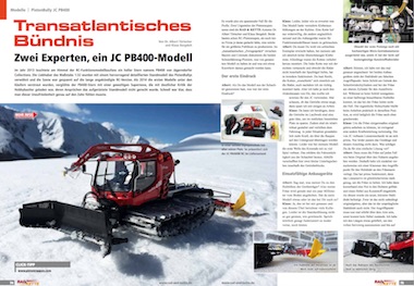
The german magazine Rad & Kette 2/2016 issued an article by Klaus Bergdolt and me about the modification of the JC PB400 with lots of advice. It's in German language.
The article can be downloaded as PDF file, with friendly permission by the magazine. Just click on the picture for downloading.
Diese Seite verwendet Cookies. Sie stimmen der Verwendung von Cookies durch Anklicken von “OK” zu. Nähere Informationen finden Sie in unseren Datenschutzbestimmungen.
This page is using Cookies. You are permitting the use of cookies by clicking on “OK”. More information can be found at our Privacy Protection.
OK