Walser
Pistenraupen
Modellbau
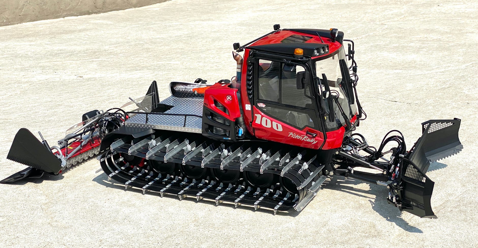
As a little brother for my PB400 ParkPro 4F I'm now building the newly introduced PB100 Park. The challenge is that body, chassis and auxiliaries are practically all completely new designs. And furthermore the smallness of the snow cat brings additional challenges in utilizing the limited space.
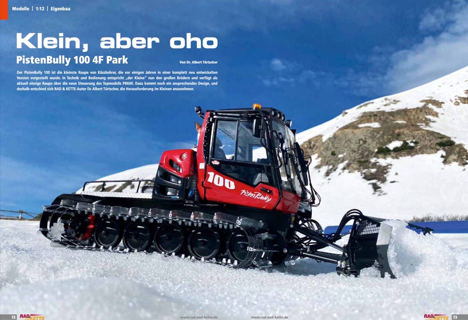
The original is also a completely new design and features all the high-tech parts of it's larger brothers, like the 4F exhaust gas aftertreatment and the new operating concept in the cockpit.
The company Kässbohrer kindly gave me access 3D data as an excellent base for creating a true scale model. By the way I have a license agreement with Kässbohrer since 2007
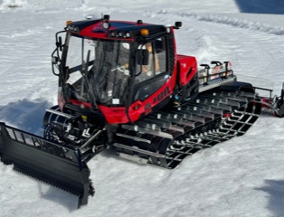
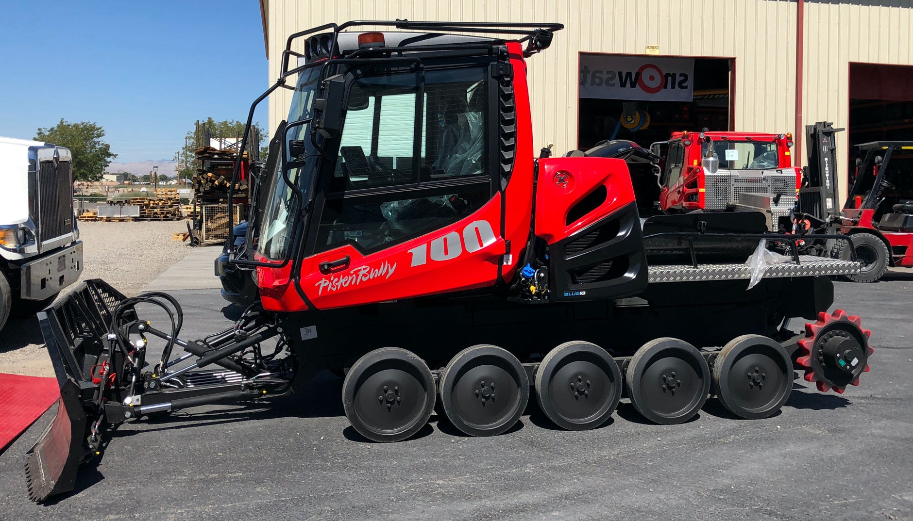
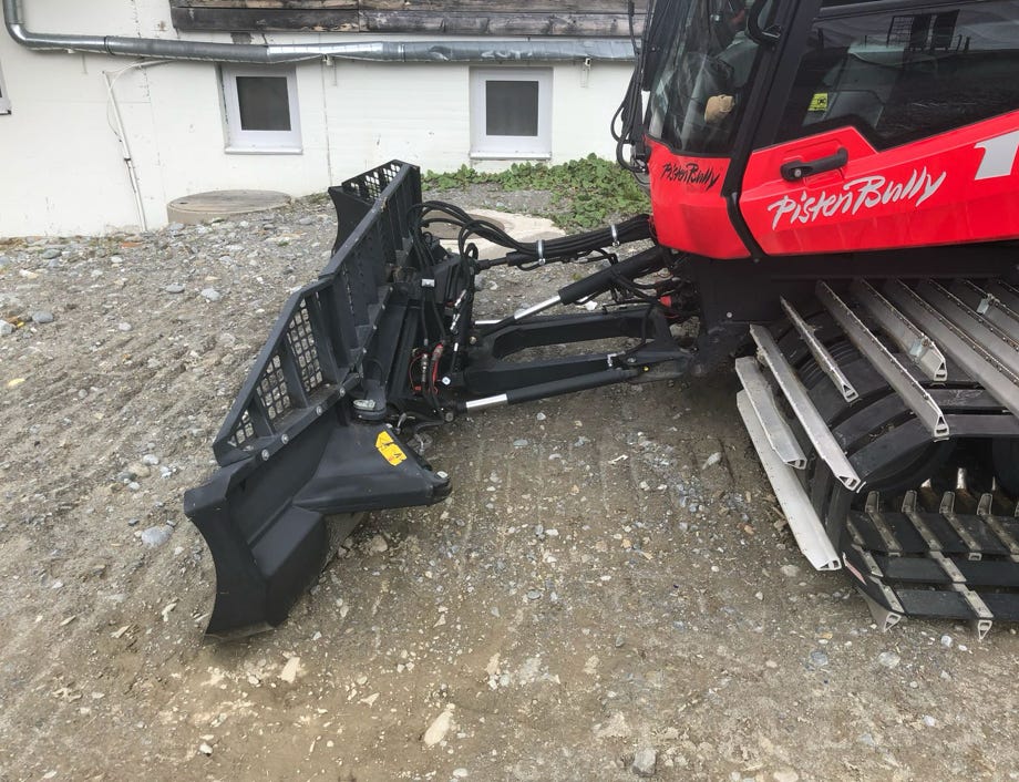
PB100 Park (original) at the Kässbohrer location at Grand Junction, Colorado
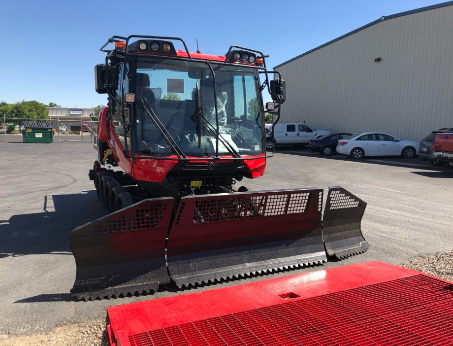
PB100 Park (original)
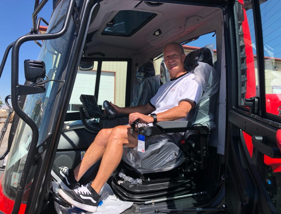
Checking out the PB100 Park :-)
End of September 2018 I could inspect a PB100 Park at the Kaessbohrer office for the Rocky Mountains. I made almost 400 detail photos. A big thank you to the great folks there, who put the PB100 in the center of the lot for me.
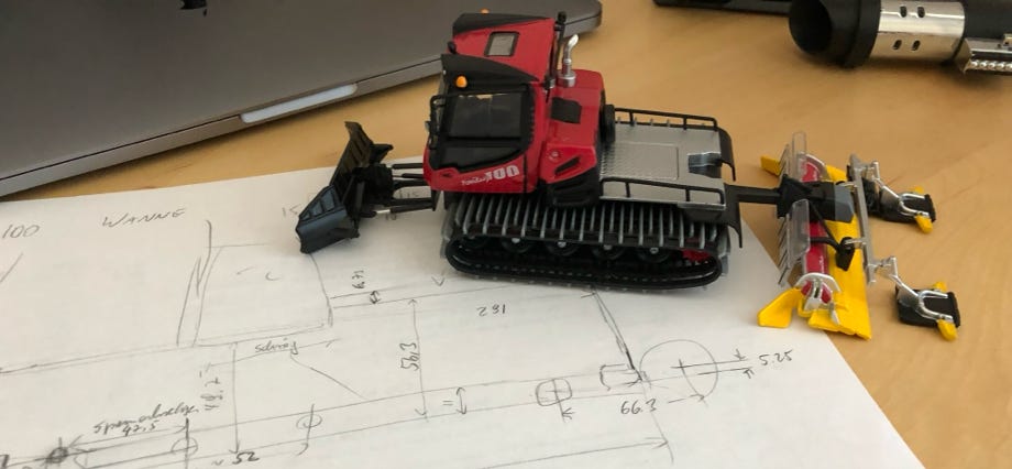
The first step is always to design the chassis as a base for the snow cat. The JC model serves as a motivator only.
Here I'm relying as much as possible on parts by Pistenking. Not only because it makes it easier, but also as they actually correspond to the original. For example the track tensioning mechanism by Pistenking is the same as at the original.
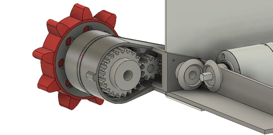
But I cannot use the flex shaft drive because the bending radius would be much too tight.
Instead, I'm making a gear set with bevel gears and spur gears, on the left you can see this in the CAD model. The gear box housing will be printed and supported by laser cut metal parts.
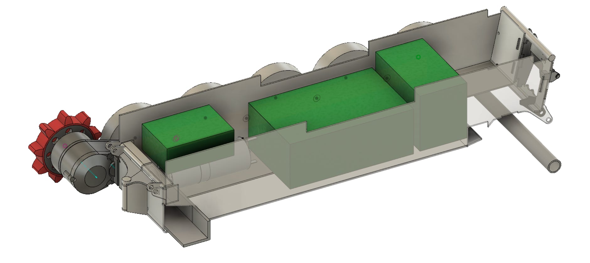
In the picture below I positioned the hydraulics components (green blocks) in the chassis for checking if they really fit. At the front is the pump, in the middle a 6-valve block (which I have available since the conversion of my PB400 ParkPro), and at the back a single valve.
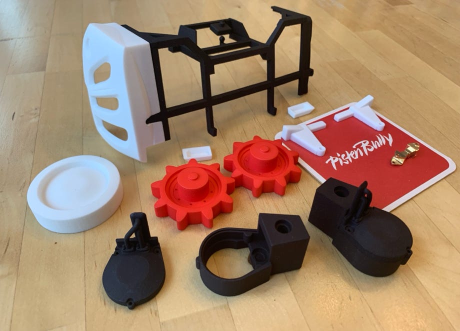
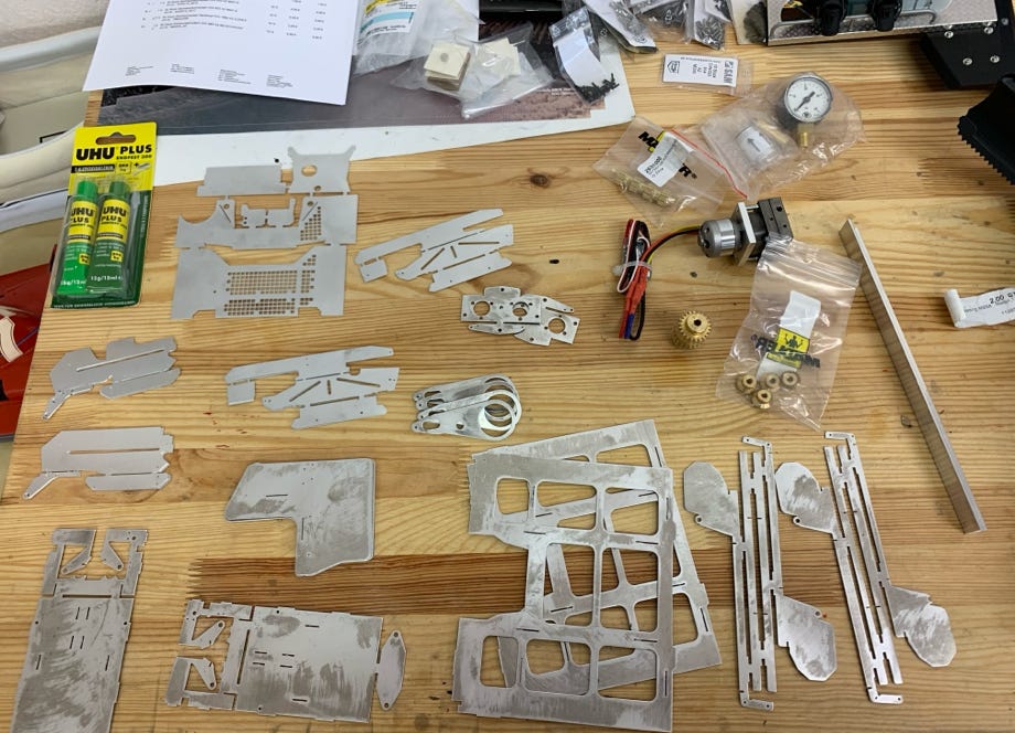
It’s always exciting when the first parts arrive: above are the first printed parts for the sprocket gear box (front black), the sprockets, the master form the wheels, the frame for the backpack, one air intake and small parts. I eventually didn’t use this air intake of sintered nylon.
The above right picture shows laser cut parts for the chassis and platform, gears and the hydraulic pump.
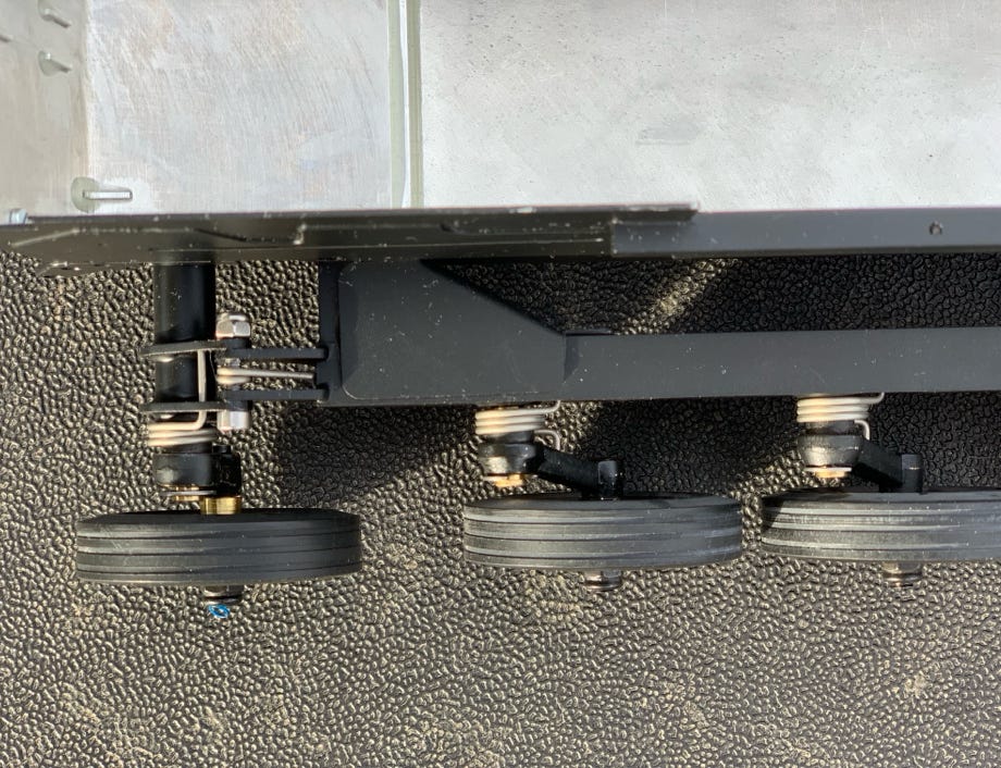
I could finish the chassis over the Christmas Holidays 2018/19. Wheel arms, suspension and track tensioner are standard parts by Pistenking of which some needed to be modified. The metal sheet parts were glued together in the proven way with UHU plus endfest 300 in the oven. Attention: the generally available version has a new formula and is by far inferior to the old version, which is now only available for commercial purposes. My advice: make sure to use the old version.
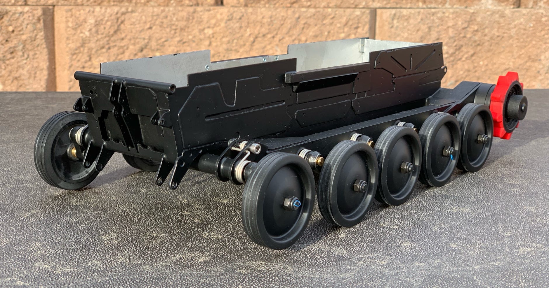
Finished chassis. The side sheets are exactly like the original.
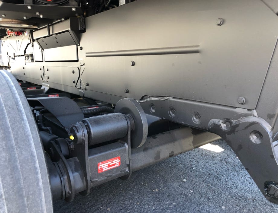
Side sheets at the original
Chassis under construction
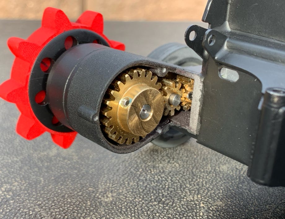
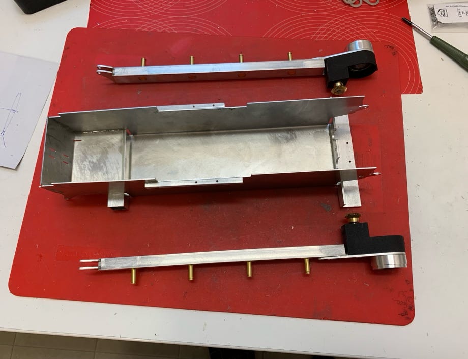
Secondary gear drive
Suspension and track tensioner
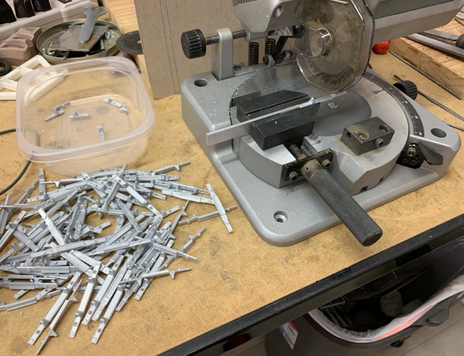
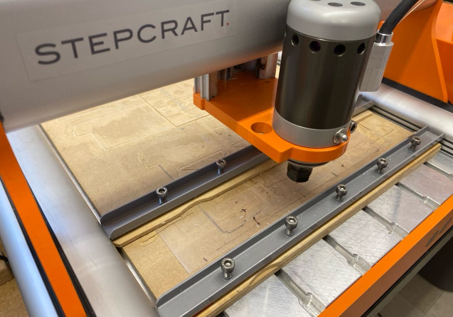
The tracks consist of Pistenking parts which again had to be modified. The cleats were delivered raw. On my Stepcraft CNC mill exact holes could be drilled very efficiently. The wheel guidance parts needed to be cut on a capping saw to fit the narrow wheels. The wheels are casted parts of PU resin which I finished on the lathe.
To assemble the track I made a device out of wood with the exact cleat distances. This allows working very accurately and fast. In addition I treated myself with a Proxxon Micro Screwdriver, a highly recommended tool especially when one has to turn in 368 screws.
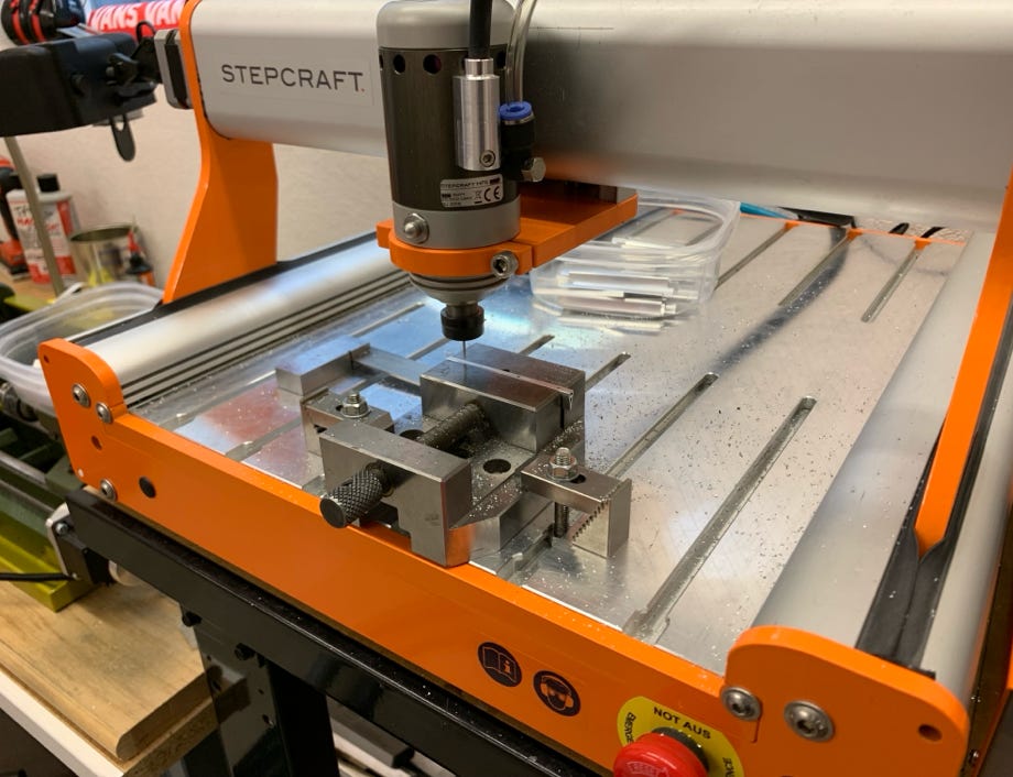
CNC drilling of the cleats
Cutting the wheel guidance parts on the capping saw
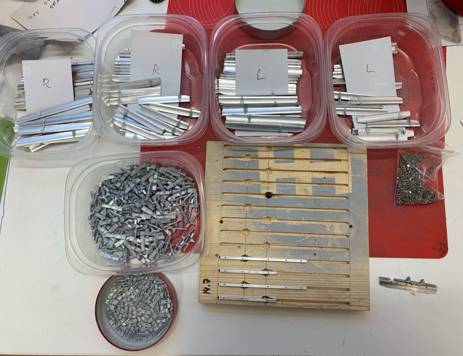
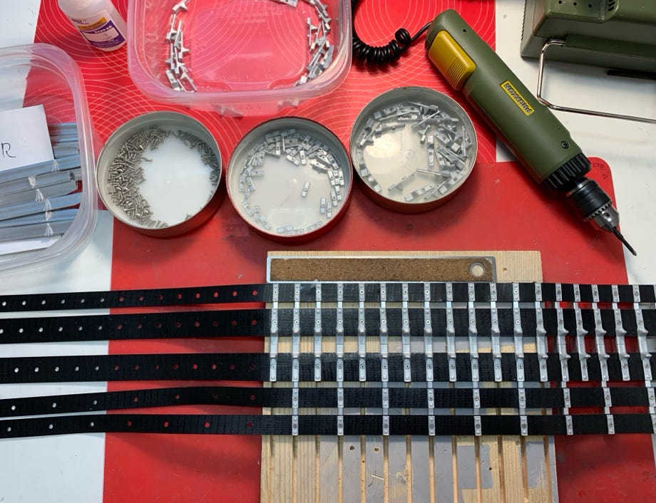
Ready for assembling the tracks
Track assembling
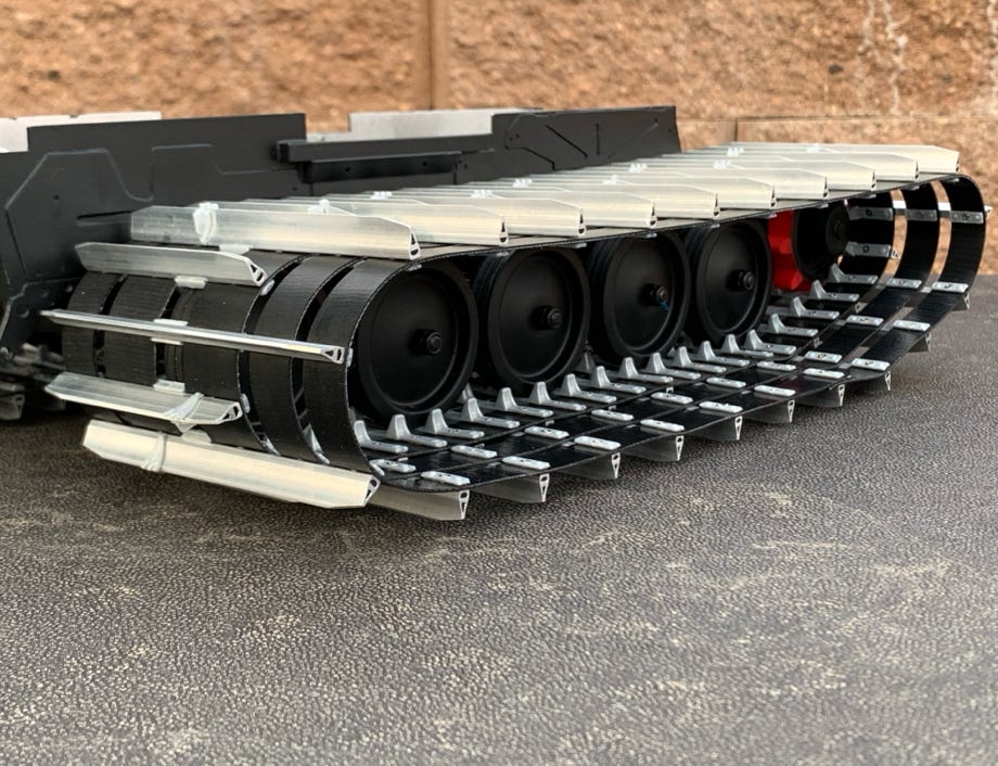
Finished tracks
Tracks at the original
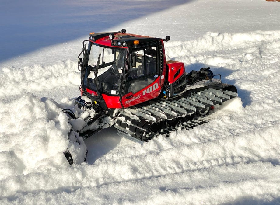
I even found a few snow patches in my backyard for the maiden drive to make this event appropriate for a snow cat. Everything worked well right on and the little snow cat moves as planned.
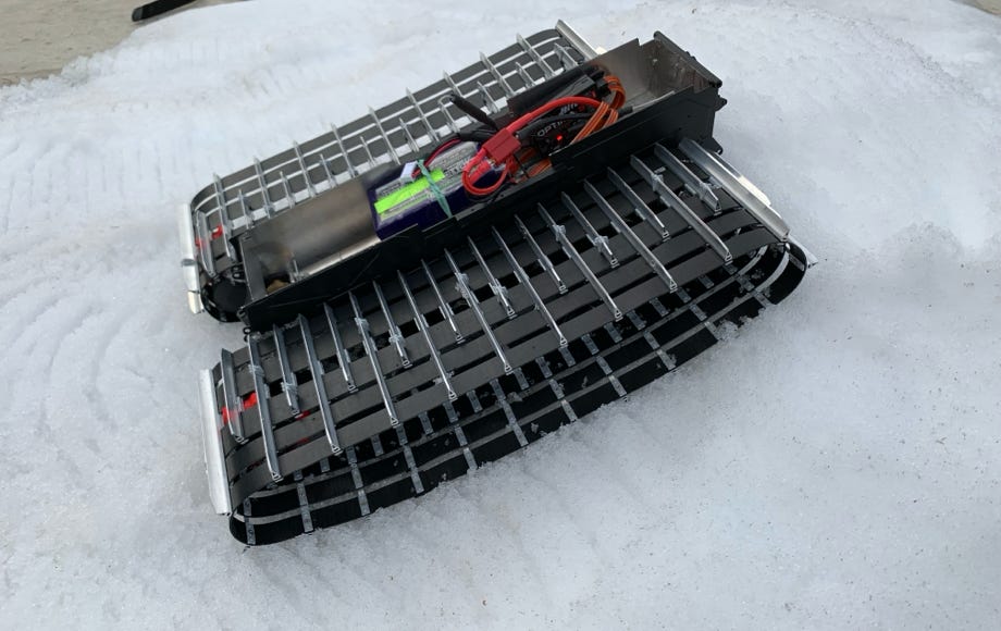
Maiden drive on Jan. 9th, 2019 at 4 pm
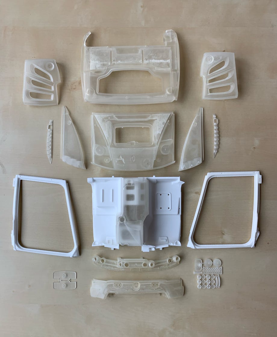
Printed parts for the driver cabin
The printed parts for the driver cabin arrived on Mar. 6th, 2019. For higher strength I had the cockpit base and side frames printed in sintered nylon. All other parts are printed in high resolution because the details are much better represented. Also I'll save quite an amount on sanding work. But they're considerable more expensive than the nylon parts. But it is really impressive how even smallest details can be seen.
I had the side air intakes also printed again because I did change the rear side to match the latest version.
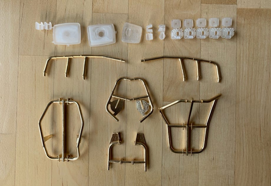
The picture below shows the printed parts for the mirrors and worklights as well as for the holders and the railing.
The brass printed parts have been combined as usual to save costs. They are then cut and for the long straight parts I soldered 2.5 mm brass tubes to them.
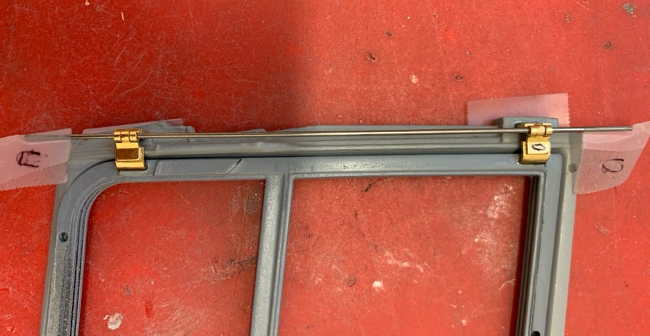
Also the door hinges are brass printed parts and correspond to the original. In order that they are on the same axis and the door can be opened I aligned them with a long steel wire for glueing.
The door is hold in place in the closed position by neodymium magnets. They are glued invisible in the cabin frame, as counterparts serve steel wires in the door frame.
The fine printed parts have to be carefully sanded to remove the unavoidable printing steps.
I first primed them with gray paint and then wet sanded with 360 grain sand paper. The gray primer remains visible in the grooves of the steps until the surface is smooth. This process had to be repeated several times.
Then I prepared the surface with 400 and 600 grain sand paper for painting.
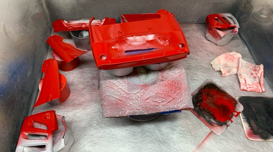
Sanding and painting required considerably more time than anticipated. At the end it were months until all parts were sanded and painted. Unfortunately there were some mishaps at painting which added time and was annoying.
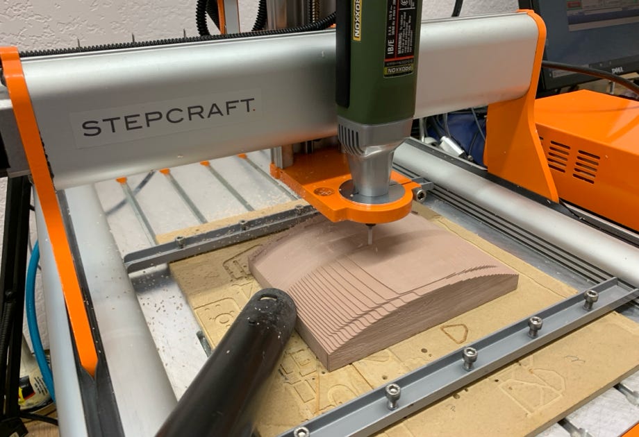
The windscreen was vacuum formed from polycarbonate. For this a mold had to be made on my Stepcraft. As done before I milled it out of Sika block, which I sanded afterwards and painted it with heat resistant paint. Then I polished it to a high shine.
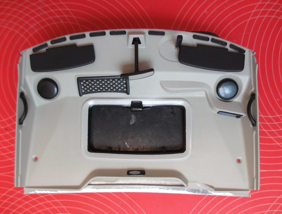
The painting and assembly of the cockpit ceeling in the picture above is finished. All black parts are separately printed pieces which makes sanding and painting much easier.
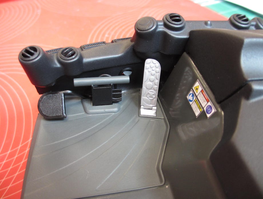
The feet area (here on the driver's side) is also made corresponding to the original. The feet rest is a brass printed part. The air nozzles are separately printed parts, so I could glue them in place in random positions.
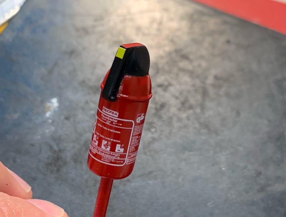
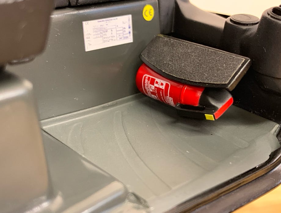
The original features a fire extinguisher underneath the foot rest on the passenger side. As I could not find a fitting one I made one myself as a printed part. Of course the right sticker cannot be missing. So I draw it according to the original and had it printed in white. Now I have more than enough such decals to open a fire extinguisher store in 1:12 and 1:8. :-)
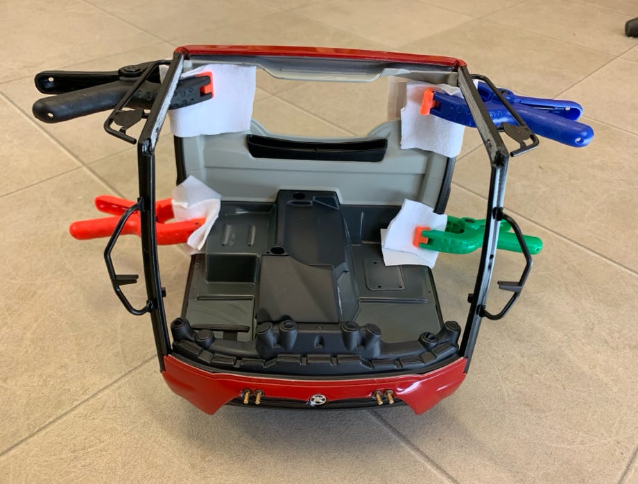
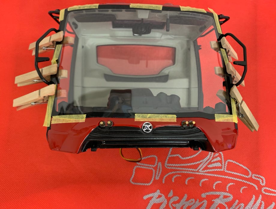
To glue the driver cabin parts together I used UHU plus endfest 300. This gave me enough time to carefully align the parts. But it needs 12 hours to cure. I glued in multiple sessions. Finally the windscreen was glued in place. For this I used a special glue for plastic scale models (Microscale Micro Kristal Klear) which was developed exactly for that purpose and which cures absolutely clear.
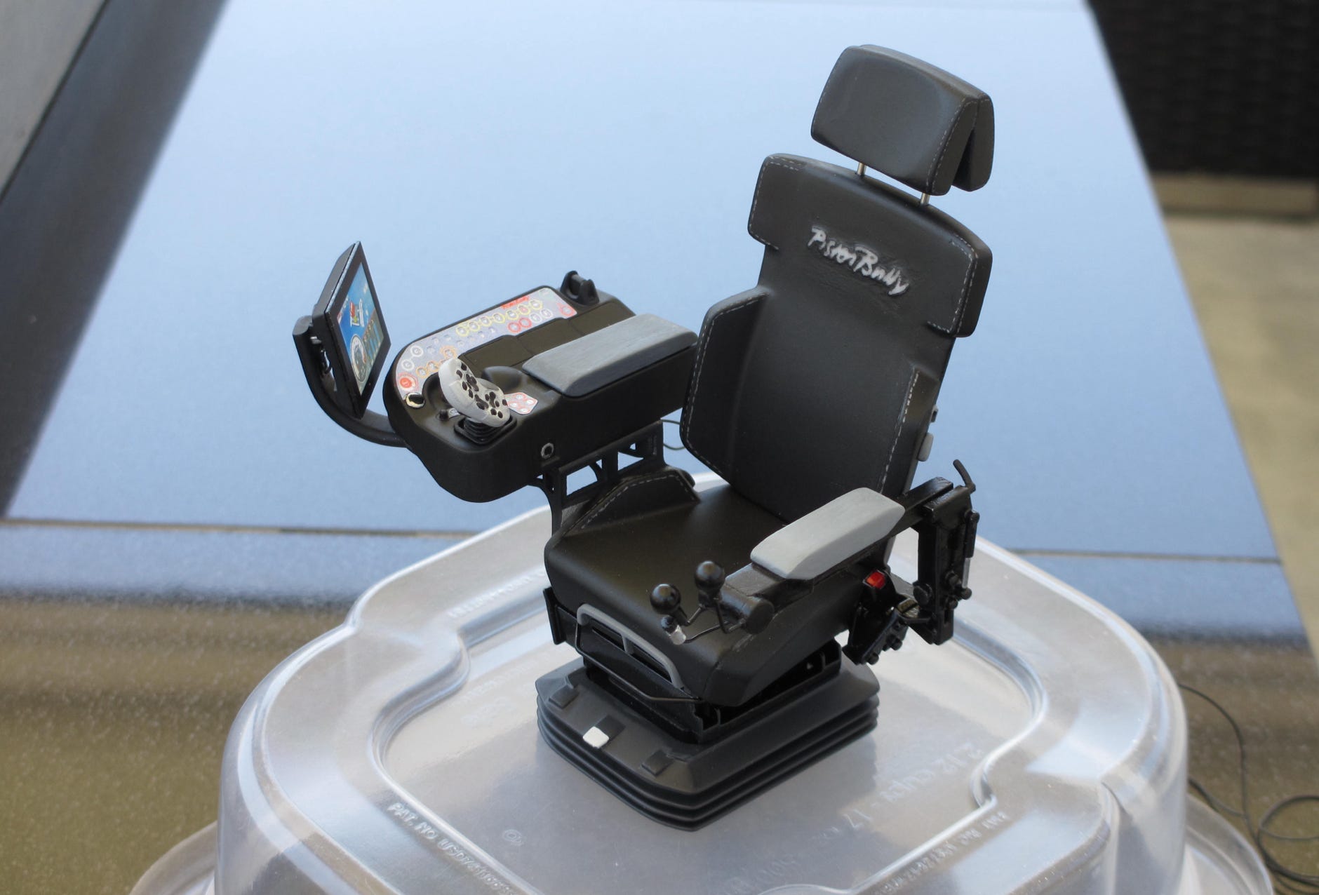
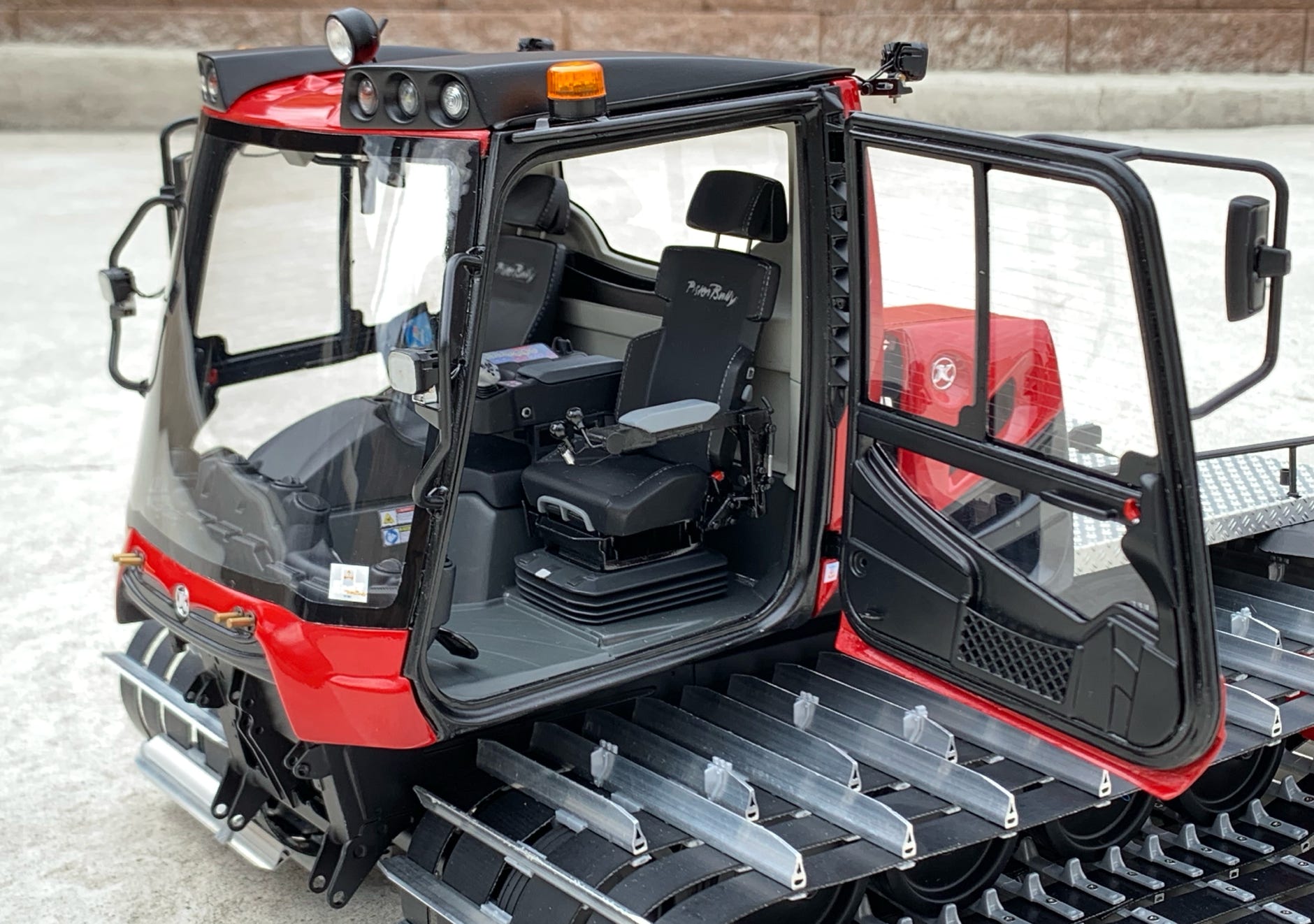
The driver seat as "'captain's chair" is not only a highlight at the original, but also at this model.
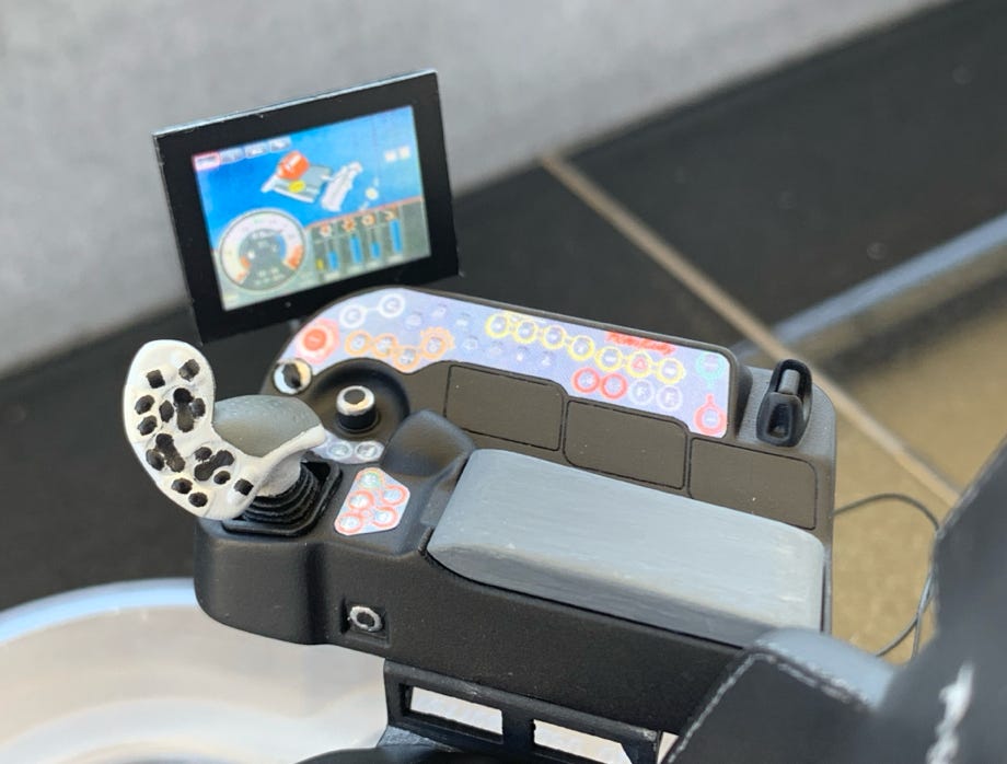
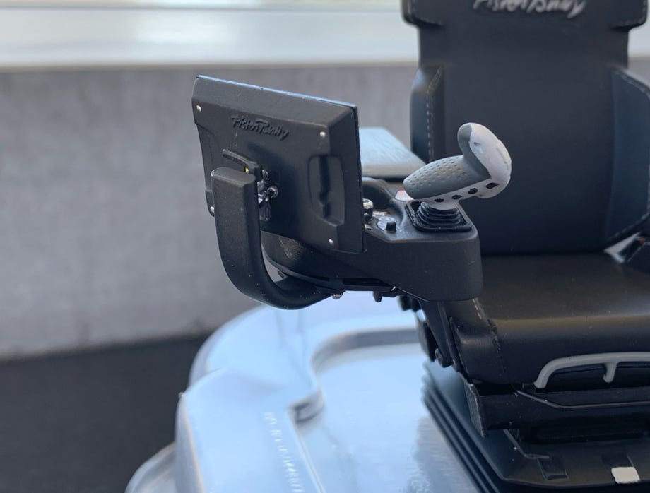
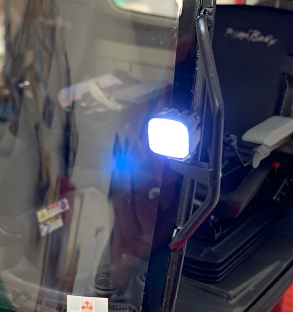
The PB100 has exactly the same newly introduced control console as his big brother, the PB600 Level Red. Of course I had to make it as detailed as possible for this model, and I'm excited that even finest details like the PistenBully logo on the screens back side are visible.
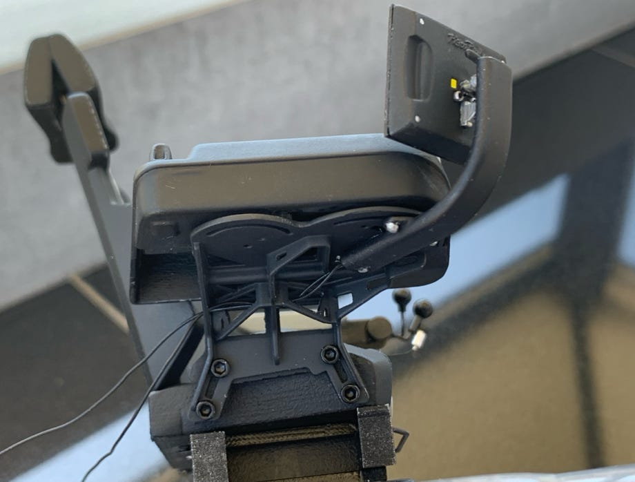
The screen is lighted from the inside by 2 SMD LEDs, the wires are passed through the hollow printed screen arm.
The console support frame is also like the original (picture below right).

The new LED worklights with their characteristic cooling fins are a real challenge in 1:12 because not much space is left to fit in a LED.
I installed an up to the minimum flat sanded 3 mm LED. Probably a SMD LED would have been easier, but I have more than enough 3 mm LEDs in stock. The worklights are installed with tiny M1 screws.
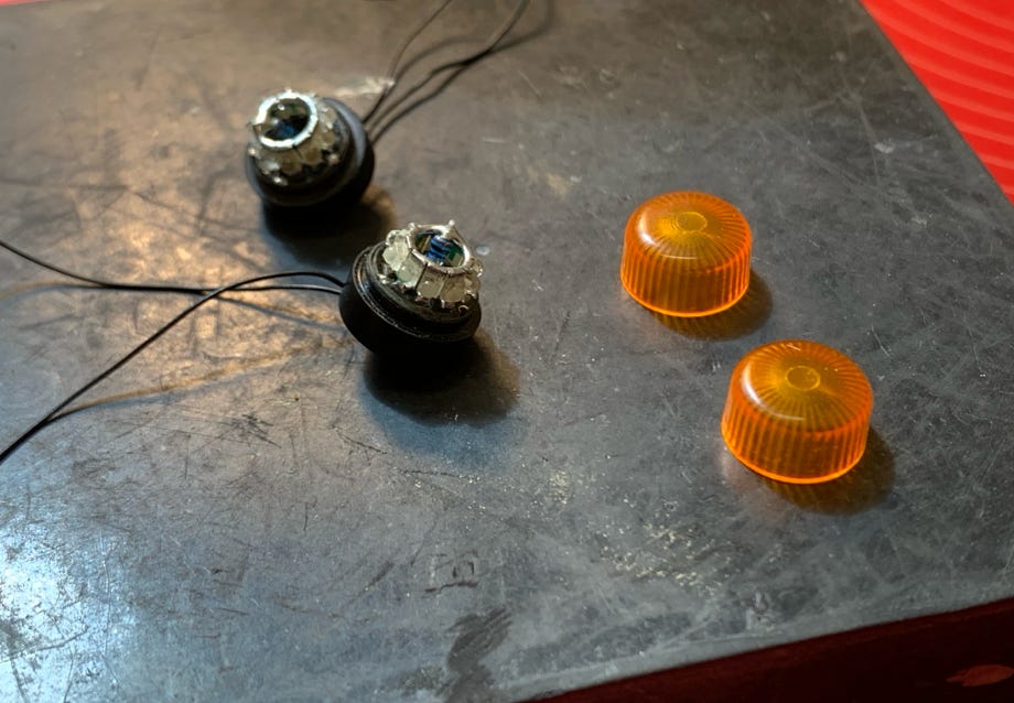
As more and more the lower and flat beacon Comet S is used at the original I had to have them for my model, too. For this I modified a Pistenking rotating beacon. The base socket had to be hollowed out on a lathe so that the LED-board would fit in it.
The orange cup was shortened and sanded flat on top and polished. Only a thin film of plastic remains on top. A really delicate modification, and all too easy the electronics may be damaged (see picture to the right).
To comfortably switch the individual light functions I'm using the Pistenking Kingbus system as in my other models. Pistenking delivered the Universal Modules "naked" without housing and plugs. Otherwise they would not have fitted into the roof. Therefore I had to solder the wires.

"Naked" Kingbus Universal Module
Flashing beacons and hazard flashers live
In parallel to the body parts I could finish all additional parts like mirrors, worklights, inner covers of the doors, seats and stickers. Therefore the final assembly with all details could be done relatively quickly.
On July 25th, 2019 the moment had come to say "Please have a seat in the driver's seat".
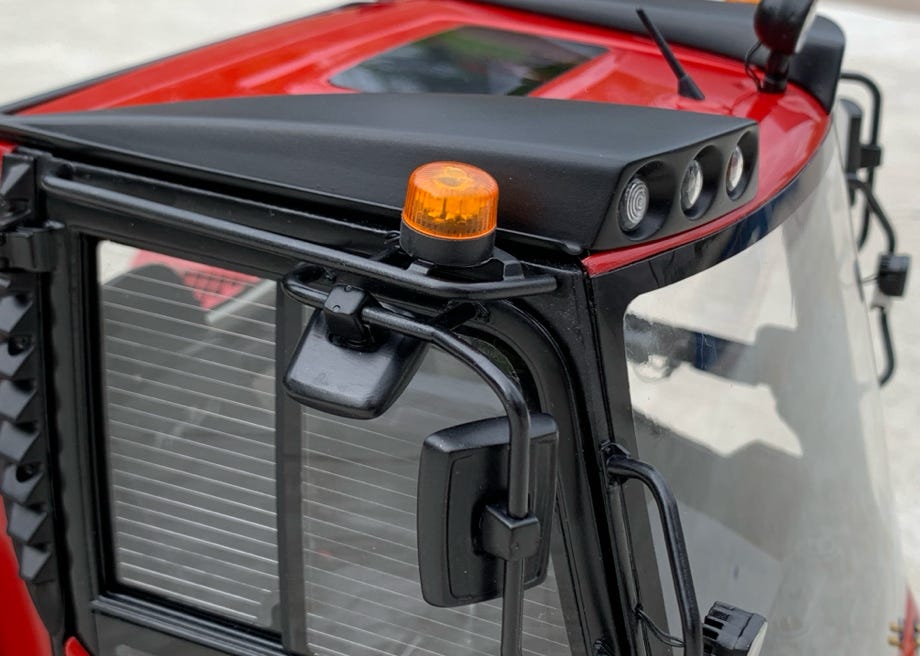
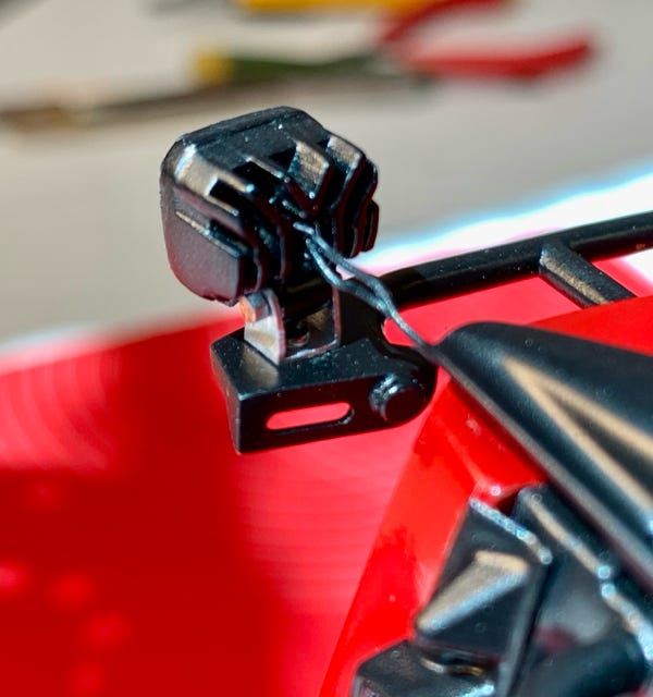
Detail view of the mirrors and the flat warning beacon
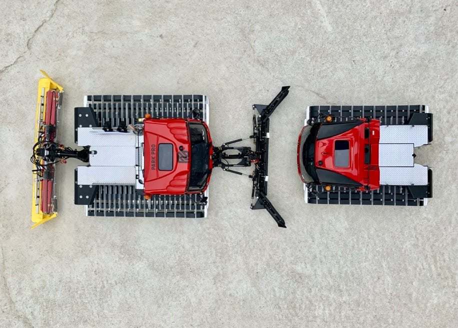
Size comparison with the PB400 ParkPro 4F
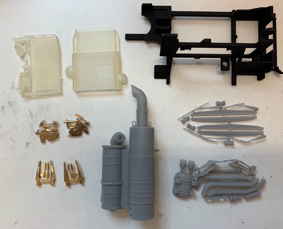
End of August 2019 the printed parts for the backpack and the wipers were delivered.
The exhaust aftertreatment system is printed with a new material in stereo lithography. The details come out really good. This material is considerable more durable than the transparent resin from which the ultra high definition parts are printed.
As usual I combined the parts to groups to save costs.
For the exhaust aftertreatment package and the cooling package I made all parts which are visible. Especially for the exhaust parts several sanding sessions were necessary to achieve a smooth surface. The exhaust pipe is silver when new but de-colors quickly in operation and gets rusty. I had to use all my painting tricks here.
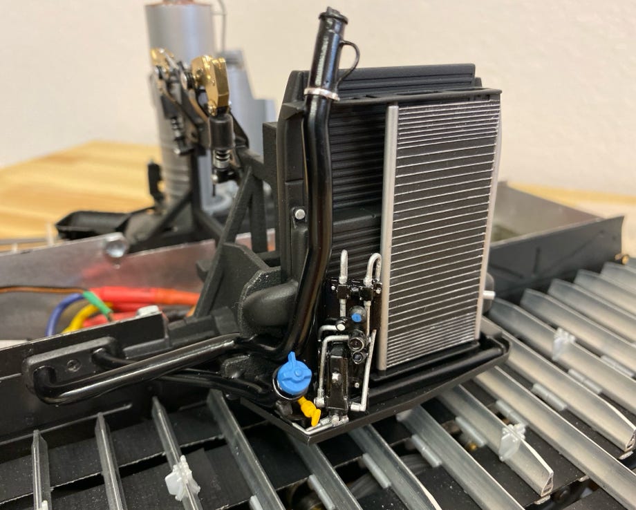
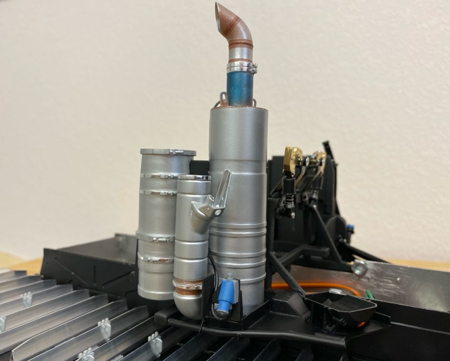
Cooling package with tank pipes for Diesel and AdBlue
Exhaust aftertreatment: left the particulate filter, in center the AdBlue mixer and right the catalyst
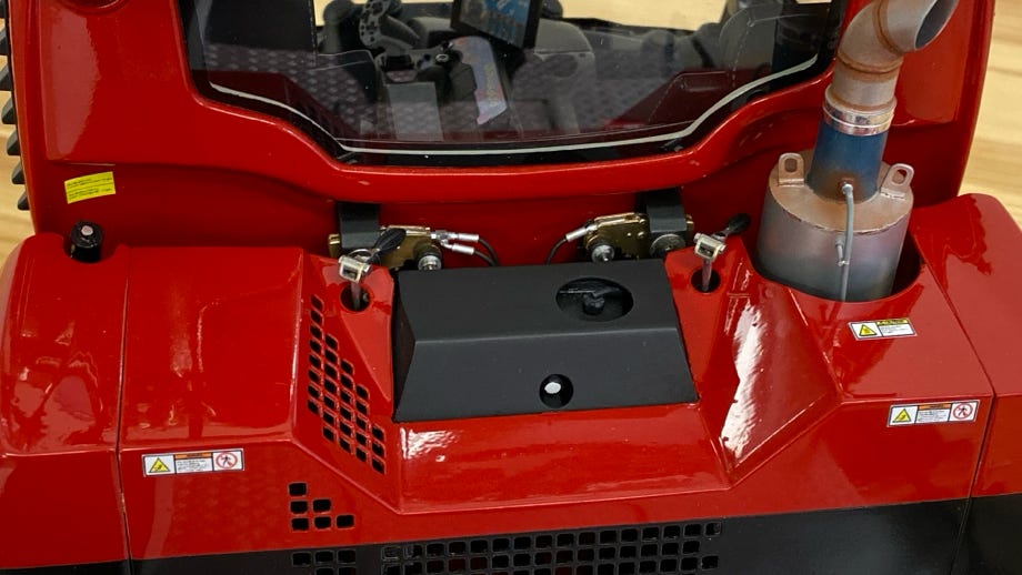
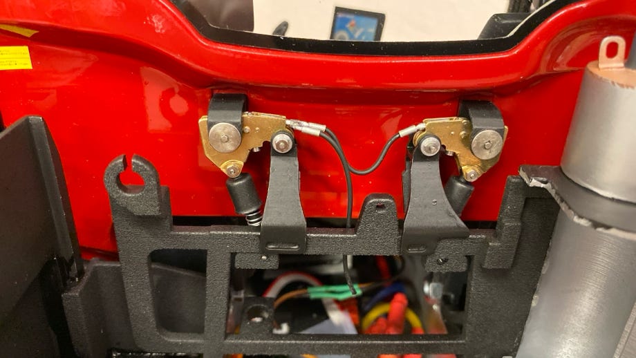
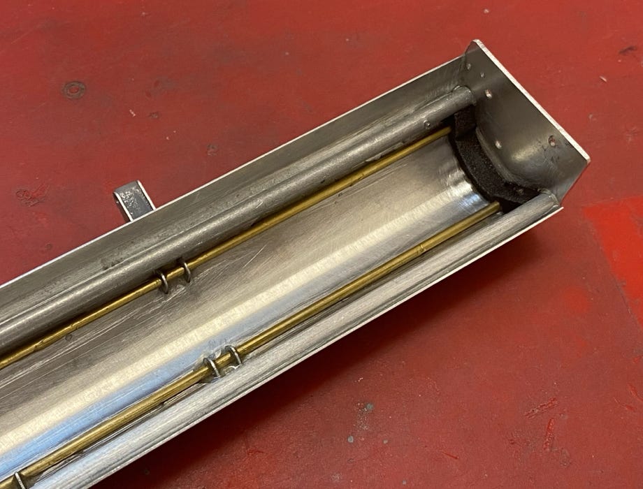
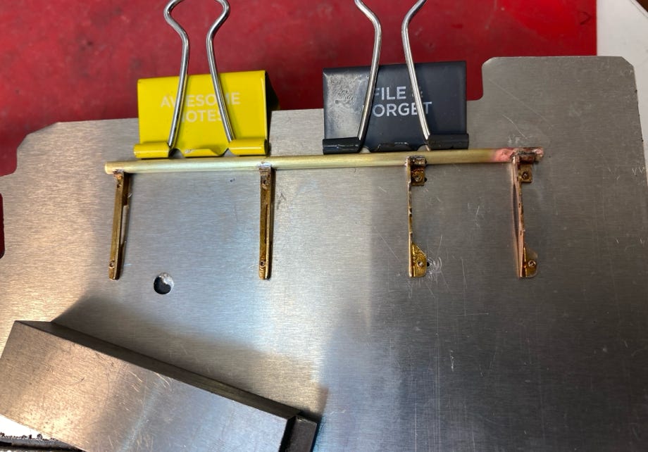
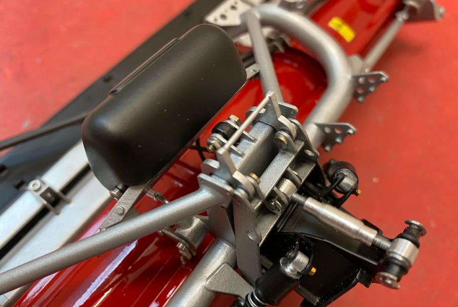
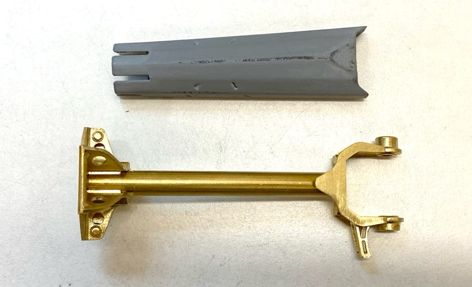
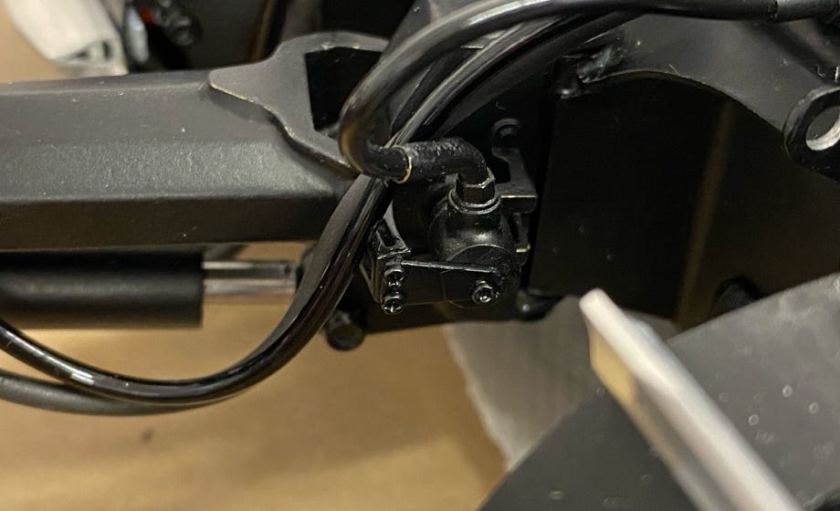
The locking mechanism for the driver cabin is visible, too, and therefore I made detailed parts of it. At the original the brackets of the cabin click into the golden lockers which can be unlocked hydraulically. The parts are moveable at the model and are pushed in place by the spring. For stability they are brass printed parts (pictures above).

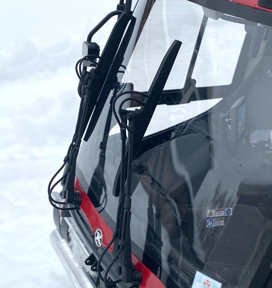
For the first time I made functioning wipers for a model.
The ScaleArt Commander offers a (interval) wiper function, so that a servo can be used for the drive.
The wipers are a detailed replica of the originals.
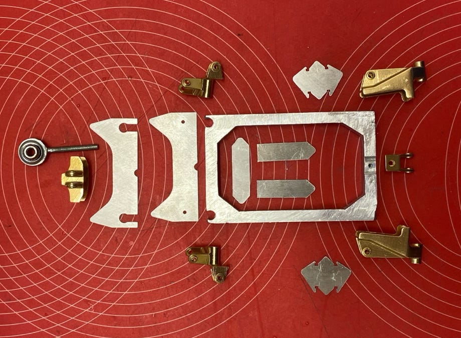
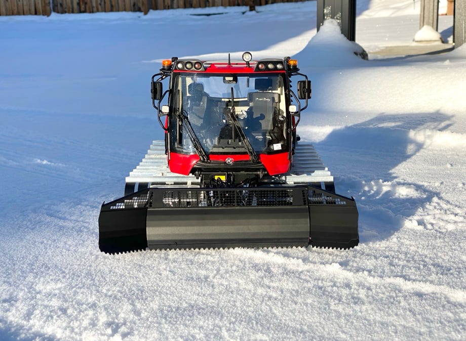
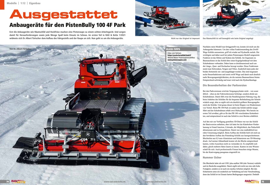
The Parkblade ist glued together from 0.5 mm aluminum sheets mostly following the proven layout of the Pistenking snowblade. The hinges are printed brass parts. For glueing it’s important to exactly line up the parts and also to ensure that the side parts can freely move. I’m using UHU plus endfest 300 (old formula) and harden it in the oven.
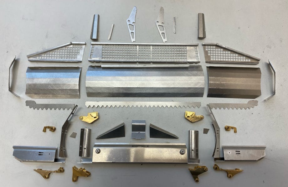
Parts for the snowblade
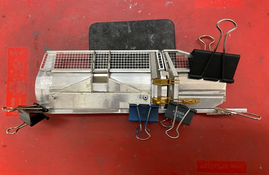
Exact line-up of the parts for glueing is of utmost importance
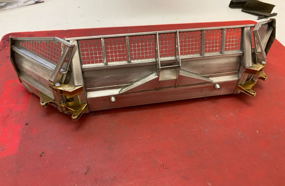
Finished snowblade before painting
Painted snow blade
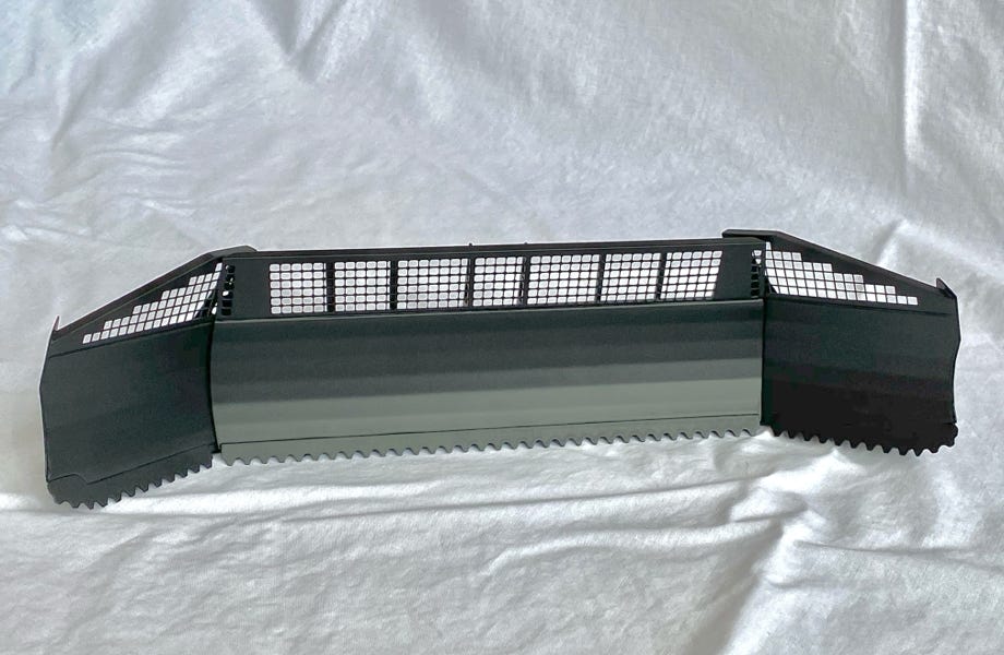
Painted snow blade
Tooth blocks on the gliding bar like the original
The pushing frame and the blade carrier are laser cut massive aluminum parts. Thin sheets create a scale look at the pushing frame. All hinges are also screwed to the frame for additional safety.
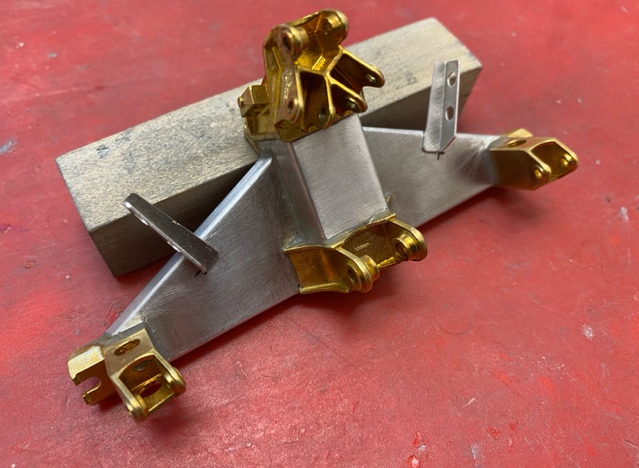
Parts for the pushing frame
Blade carrier
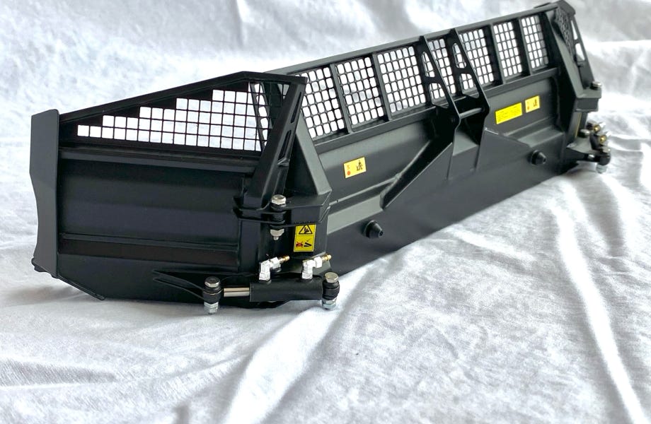
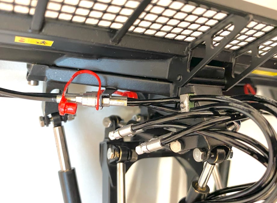
The hydraulic cylinders are made in the same way as those of my ParkPro (see Hydraulics). For the hydraulic fittings I went new ways and had them all printed of brass parts. Only that allowed me to achieve my claims for an original scale look. But still I had to make compromises for the first time on this model, because smaller hydraulic hoses than 2 mm is impossible. And they finally define the fitting sizes. Tiny 1 mm holes had to be drilled into the brass parts, and sometimes a drill bit broke. This piece of hard metal cannot be removed, but based on experience I wisely ordered twice as many fittings.
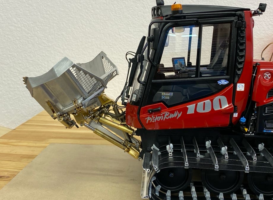
Dry testing of the blade movements: uppermost position
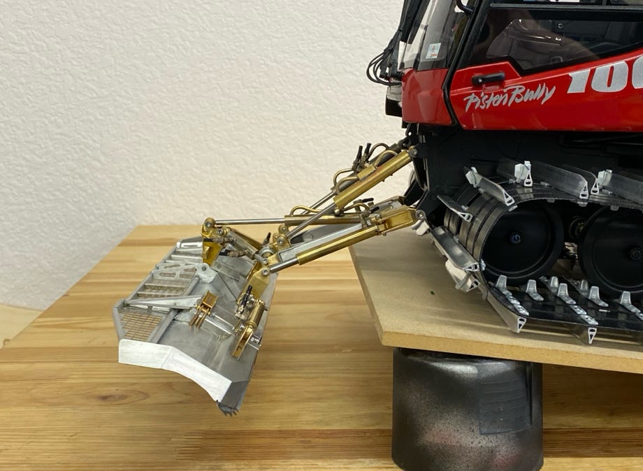
Dry testing of the blade movements: lowest position
With a dry test I could check the full moving range and nothing blocked or restricted the motion. After that I could install the hydraulic components. Prior to that I thoughtfully figured out the exact arrangement because every millimeter matters in the small tub.
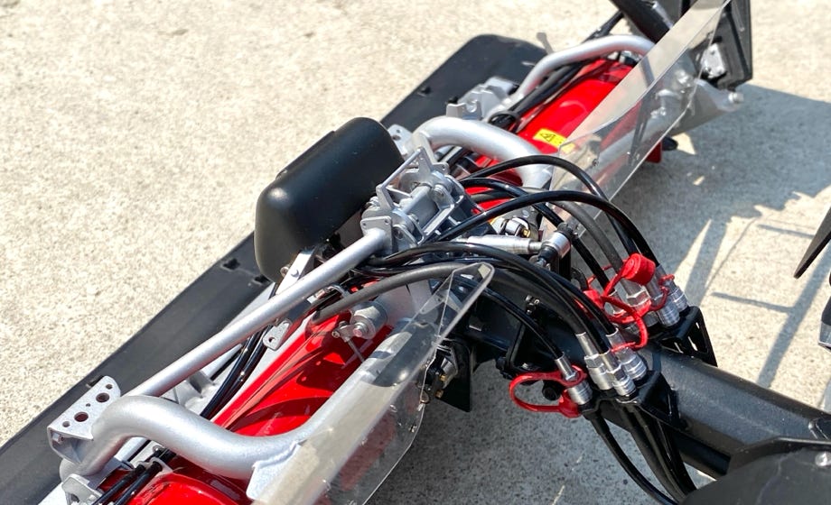
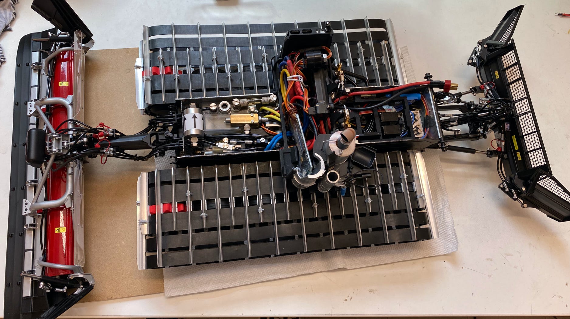
The oil tank is a complex printed part to make best usage of the space above the driving motors. It also holds the pressure regulator and the valve for lifting the tiller. I had it printed transparent to easily check the oil level. The picture below shows the completely connected hydraulics but without the hoses for the cylinders. The pump is by Modellbau Kampshoff (he uses Jung pumps) and the valves are by Modellbau Meinhardt.
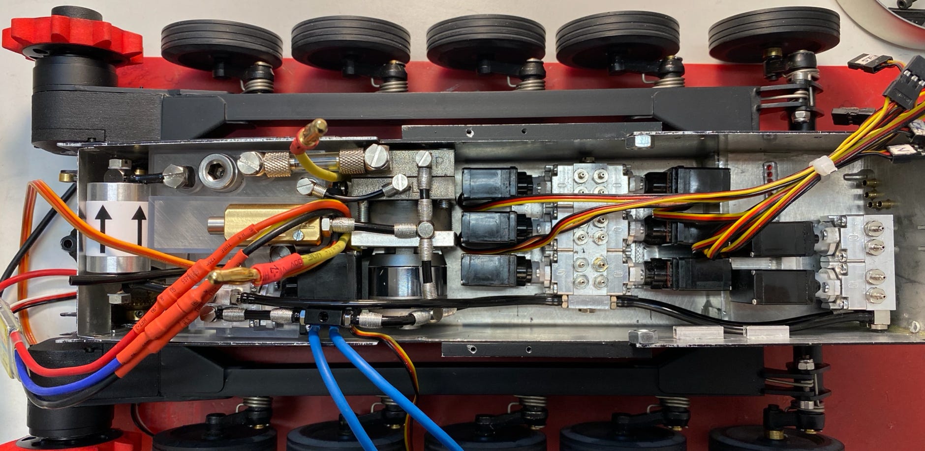
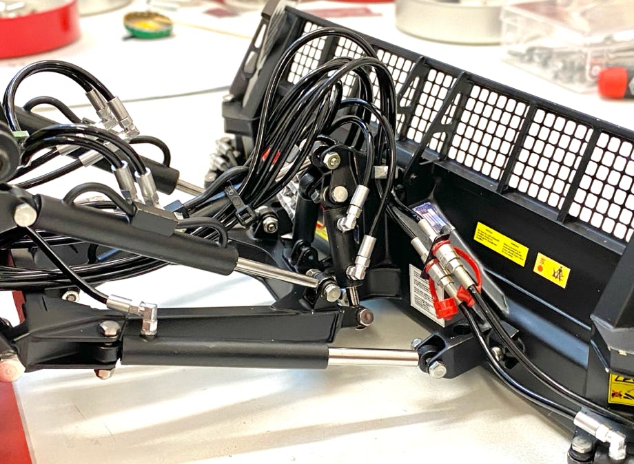
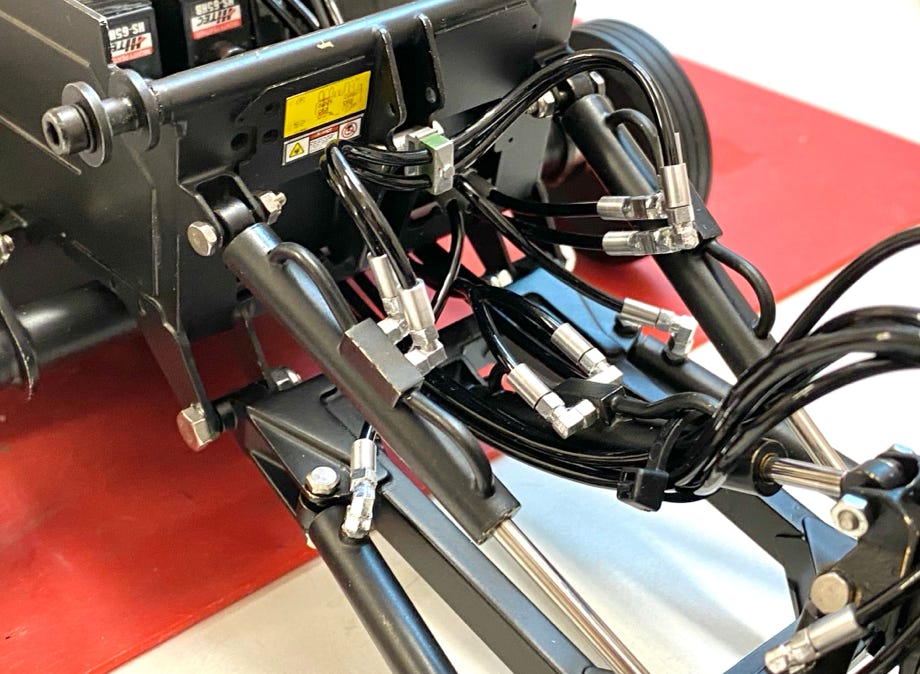
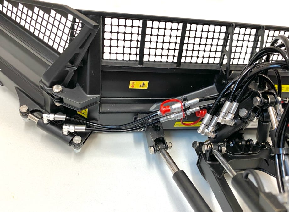
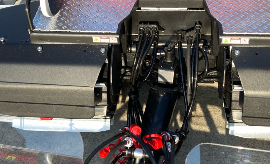
The arrangement of the hoses follows the original as much as possible (see pictures above). Then came the exciting moment of the first commissioning of the hydraulics: everything worked right from the beginning and all cylinders and connectors were tight. Only one side blade cylinder had a small leak at the connector due to a failure when soldering.
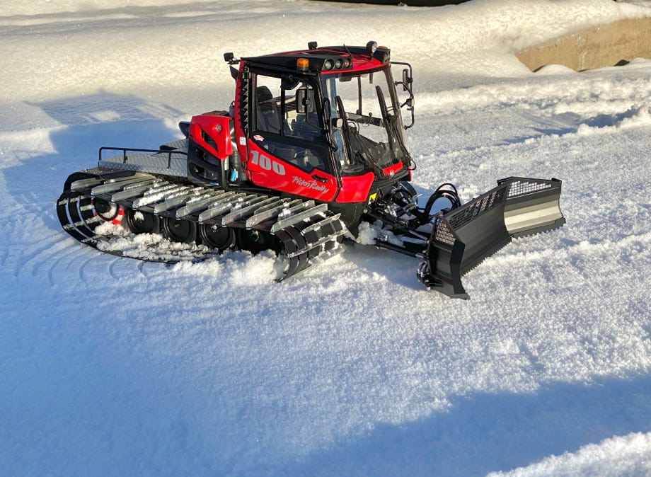
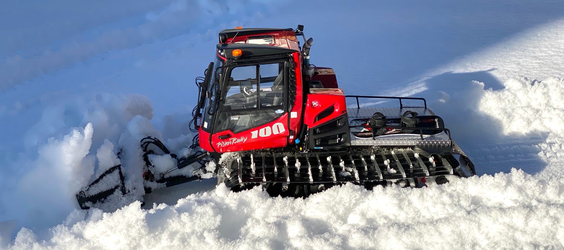
Just in time there was snow fall in Denver, Colorado. I could use the early morning hours of March 21st, 2020 for a first test of the snowblade and the hydraulics in real snow. Even this small snow cat can move considerable amounts of snow!
Here’s a short video about the first test in the snow:

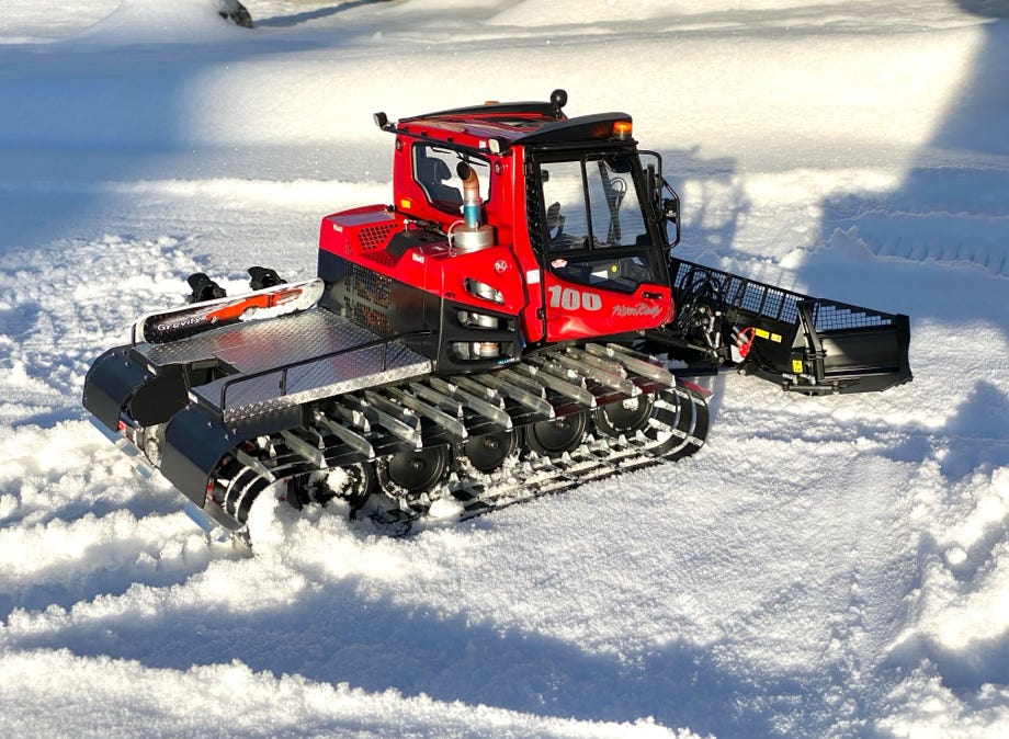
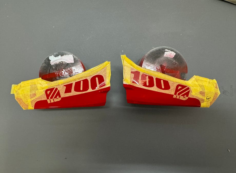
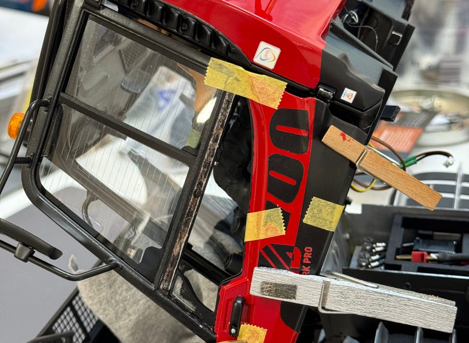
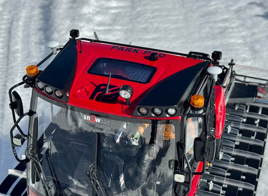
At the Interalpin 2023, Kässbohrer presented the PB100 in the ParkPro version, with the corresponding paintwork. That was reason enough to repaint my PB100. I reprinted the door panels and painted them red-black. A delicate matter was removing the old door panels and also gluing the new ones on. An operation on a living object, so to speak. And finally it was equipped with snowsat.
The rear tiller is a complex part at each snow cat and thus a challenge for a modeler. By looking at the photos I had at hand I could identify at least four different variants of the tiller. Additionally it is also available in three different widths. My 3D data included the very first and smallest version. For a recent model I wanted of course use the latest version. Upon request I got a drawing from Kässbohrer of the just presented newest tiller.
Different to the totally designed AlpinFlex Tiller of the bigger brothers the tiller of the PB100 consists of a one piece tiller wheel with a simple sheet metal housing which is basically the same for all versions. Since version 2 the side finishers are attached by a rather complex frame and thus independent of the tilling depth.
After a deep analysis of the complex frame design I decided to use mainly printed brass parts. A part of the main frame was printed from fiber enforced nylon to save costs and weight. Unfortunately printed brass parts are not cheap, but I did want to make any compromise in regards to stability.
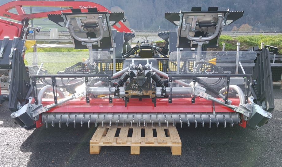
Latest version of the tiller of the original (Photo: Adrian Humbel)
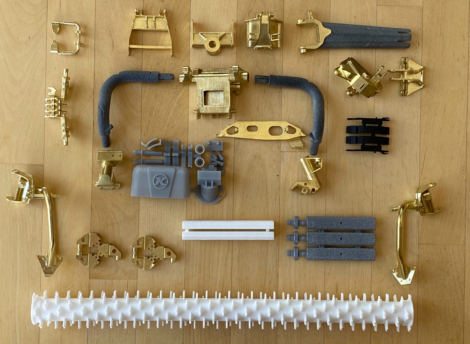
Printed parts for the tiller and the rear attachment carrier
The head of the tiller consists of several parts: the centering head, a swing arm and the frame center piece (see pictures below). A sheet metal part is glued into the rectangular hole. There must be an opening, otherwise it would not be possible to print a hollow brass part.
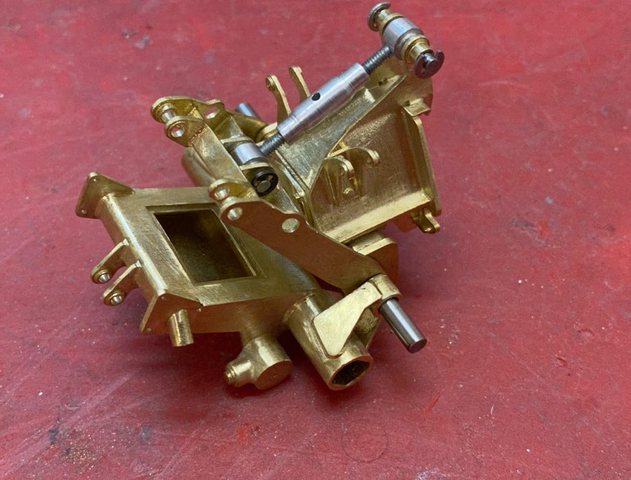
To achieve a solid connection between the plastic and brass parts I used 3 mm round steel rods (see picture). The parts have been glued together with UHU plus endfest 300 which results in a very solid and stiff frame.
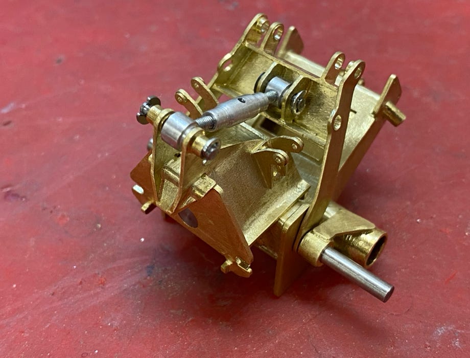
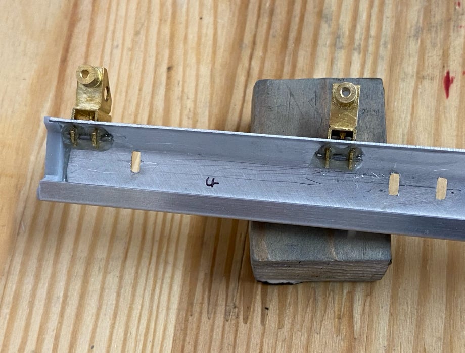
The tiller box consists of laser cut and bended aluminum sheets. Glueing is good, but positive locking is better, therefore I used 2 mm brass rods as pins for the mounting frame. In the same way the holders for the finisher were secured (photos below).
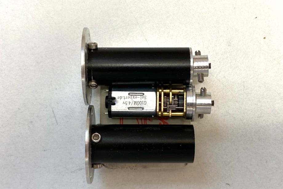
Driving the tiller wheel is done by the proven method of inside gear motors (see photo). The tiny motors with 10 mm outer diameter are mounted in 12 mm aluminum housings. They also serve as the bearings for the tiller wheel.
I used a motor on both ends to achieve twice the torque and also to have a balanced tiller.
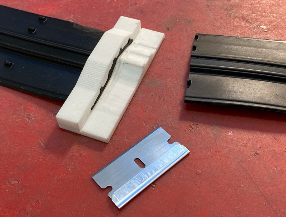
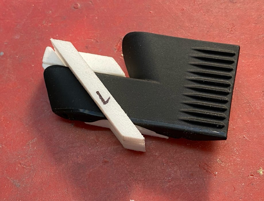
The finishers created quite some head ache because these flexible parts are anything but easy to manufacture. But the latest version of the tiller which was presented in fall 2019 was like winning the lottery for me: Kässbohrer was using the finishers of the AlpinFlex Tiller! And these are readily available at Pistenking. :-)
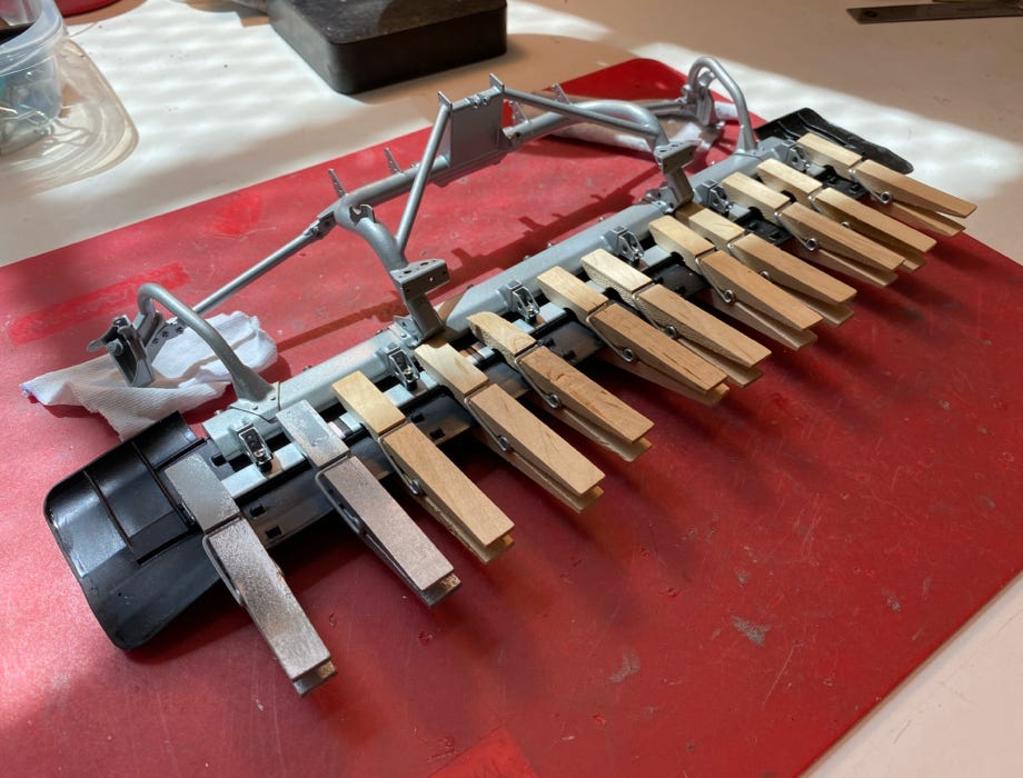
The only problem: they are too wide, so two panels have to be cut out. For a clean cut (and glueing) I had a fitting form printed. Also for the additional finishers a cutting form was used as they had to be shortened a bit, too. The parts can be glued nicely with super glue. The main finisher was glued with Pattex Repair Gel and many clamps to the holding bars.
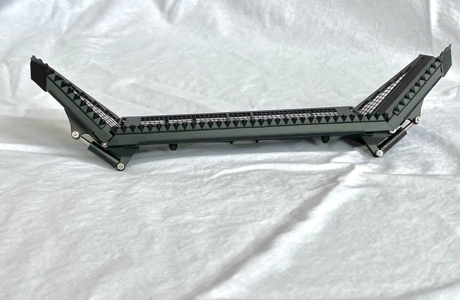
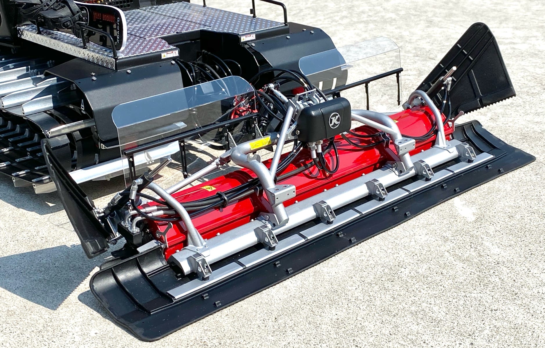
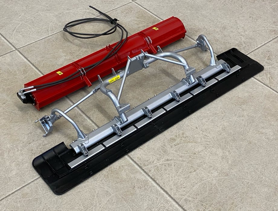
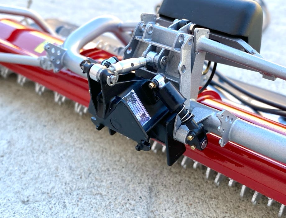
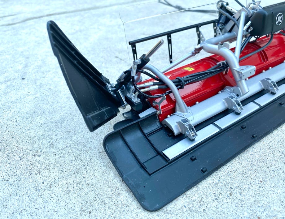
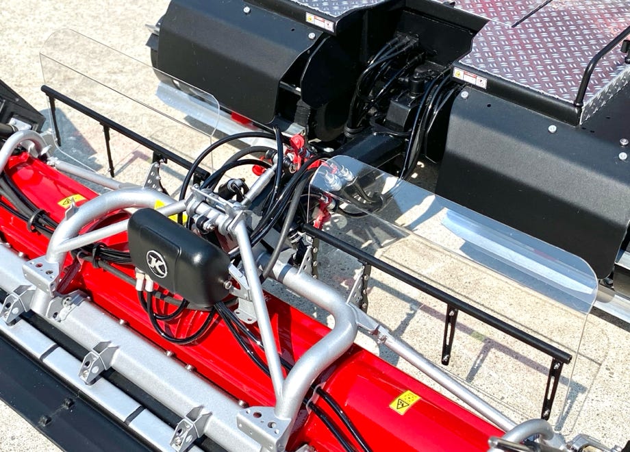
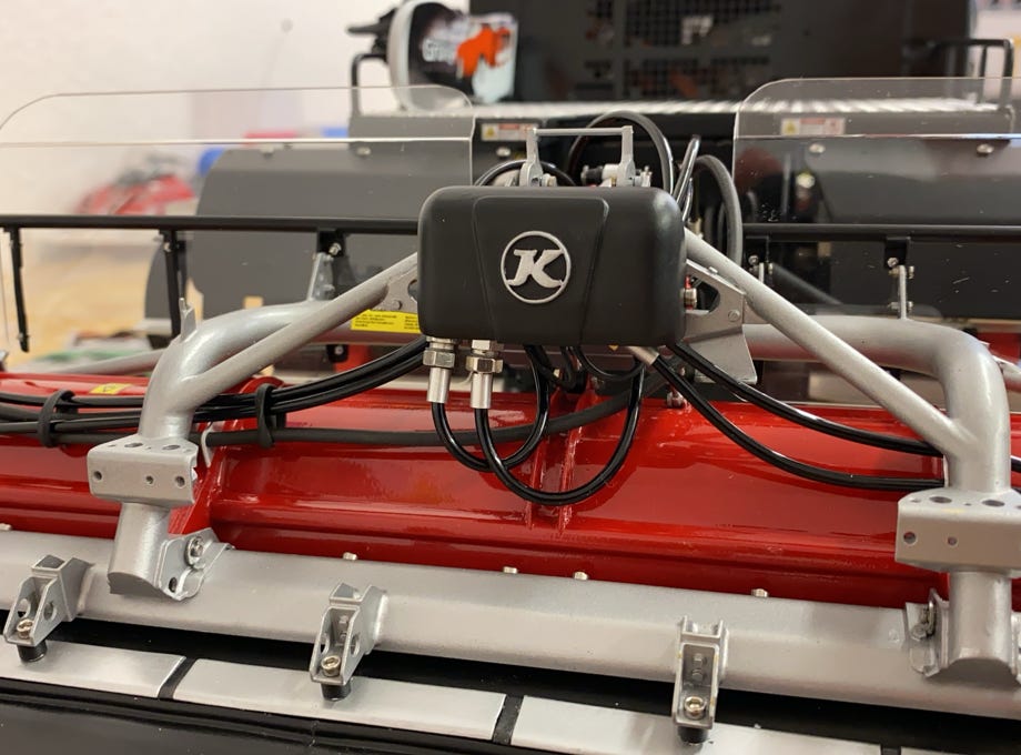
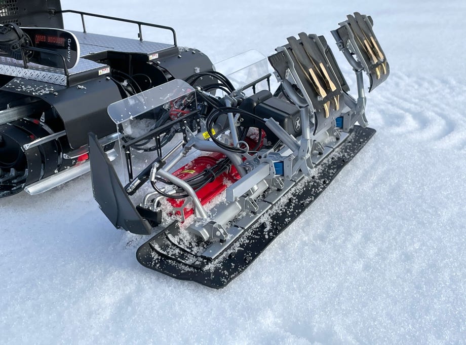
The picture below shows nicely the design of the tiller: the red tiller housing is attached to the silver frame at the rear and with a hydraulic cylinder for regulating the tilling depth at the front.
The frame work for mounting the side finishers can also be seen very well.
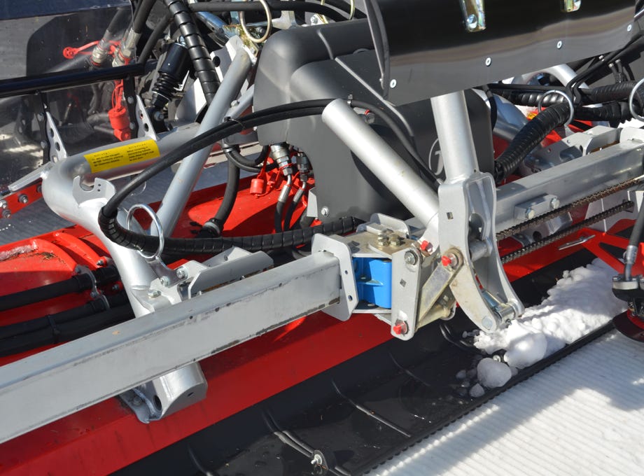
Electrical power is supplied to the tiller motors by black silicone wires which look exactly like hydraulic hoses.
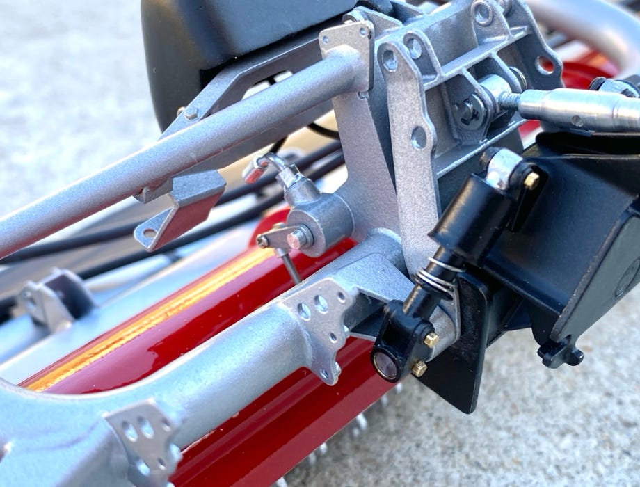
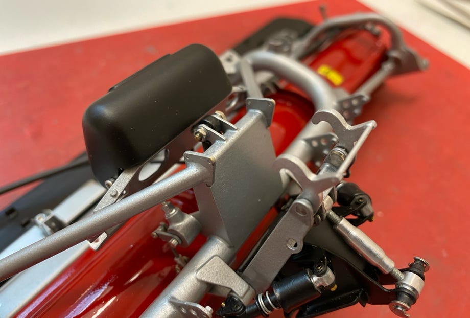
The tiller head with the spring elements can be seen here. Even smallest details like the angle sensor for the tiller depth are present.
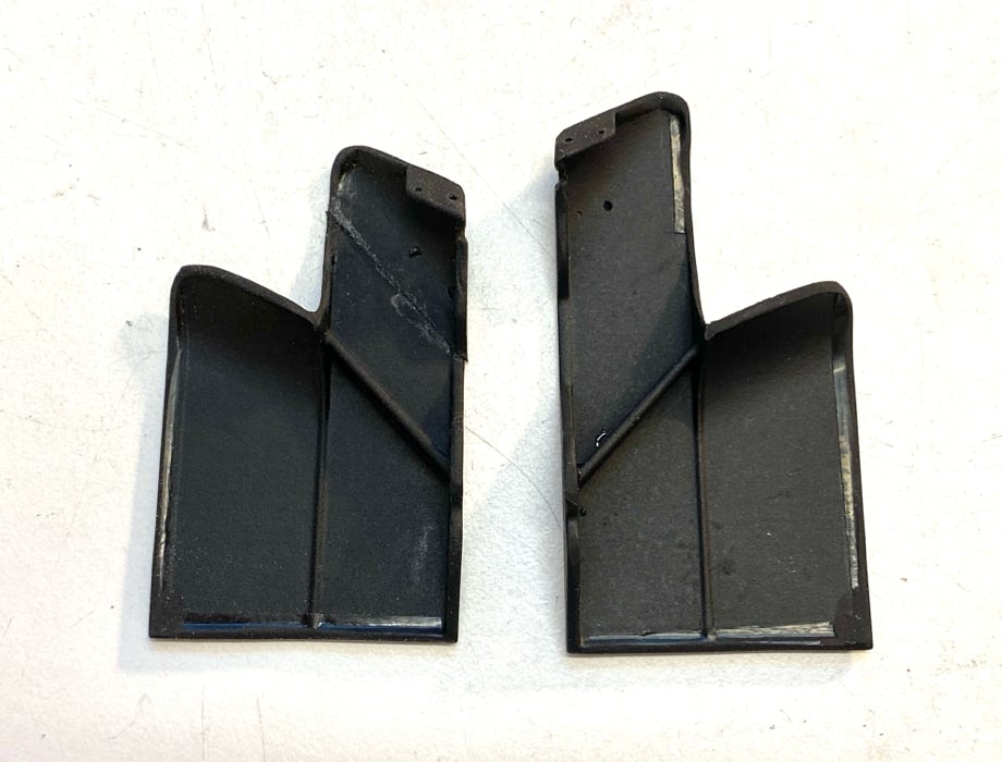
The Pistenking side finishers need to be cut a bit because at the PB100 they are not actuated by a horn but by a fixture. The original cylinders have a piston rod that extends at the rear end to stabilize the piston against side forces when fully extended. I wanted to have this at my model too, and it’s not a big deal as the same sealing has to be installed at rear end as on the front end. But I’m not aware of any such cylinders for a model, thus this might the first of it’s kind.
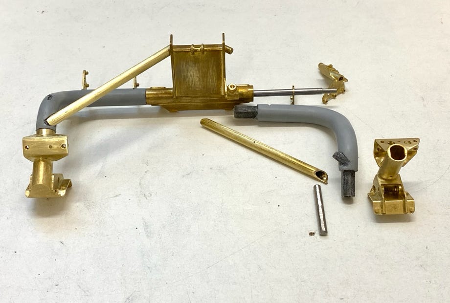
The rather delicate frame for the overthrow protectors was soldered from printed brass parts and a brass tube. For exact positioning I drilled holes into an aluminum sheet with CNC on my Stepcraft. The overthrow protectors from Lexan were drilled the same way.
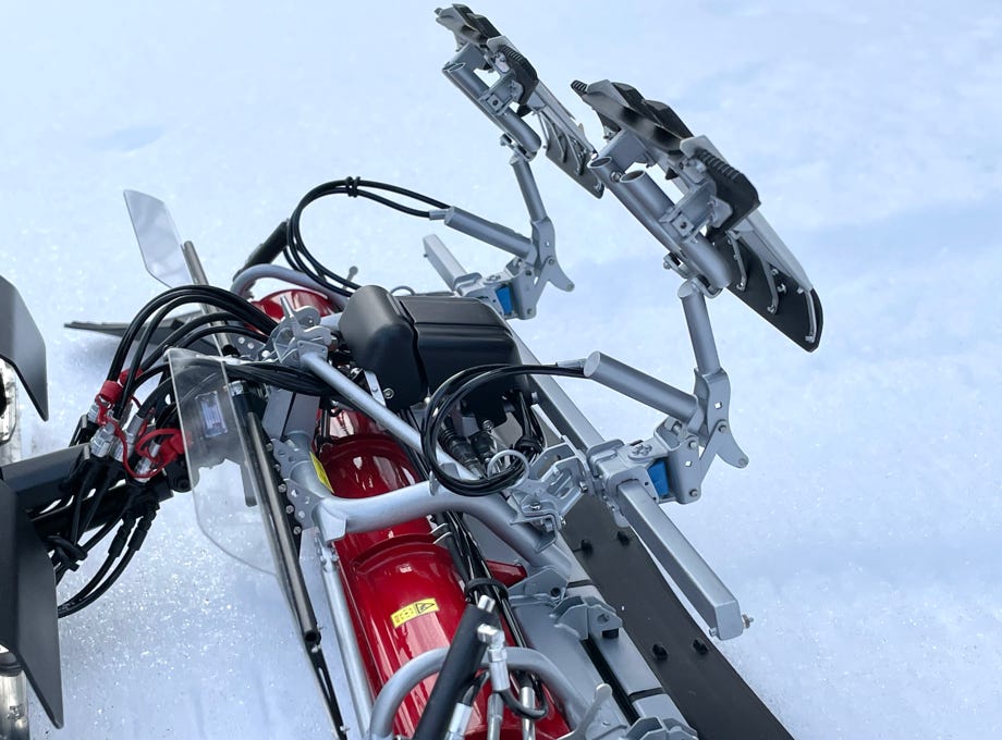
On top of the centering head are two clamps to fix the tiller in position for working in the park. In their open position the tiller can tilt downwards when being lifted. The tilt angle is limited by a stop. I realized this function also at my model. In the pictures below the open and closed position can be seen.
I glued a brass tube inside the lifting arm of the rear attachment carrier to increase the stability. Although the printed part from fiber enforced nylon would have done as well. But rather safe than sorry.
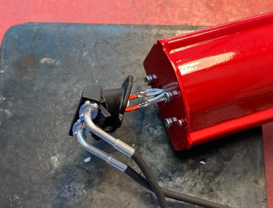
The brackets for the hydraulic quick connectors are printed brass parts and glued to the lifting arm. The connectors are dummies, the hoses are simply passed through.
The connection of the hoses to the tub are as much as possible the same as at the original. I did make the angle sensors at the rear of the attachment carriers in true scale detail.
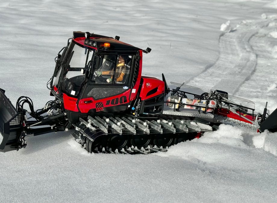
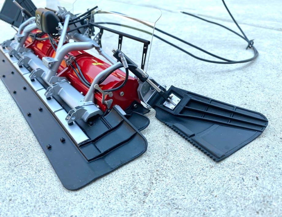
On August 19th, 2020 I could finally finish the PB100 Park. This project kept me busy for almost exactly 2 years.
The available space in the tub is used up entirely. As I mentioned at the beginning this was one of the challenges. A lot of planning and tinkering was needed to implement all this technology in the rather small snow cat.
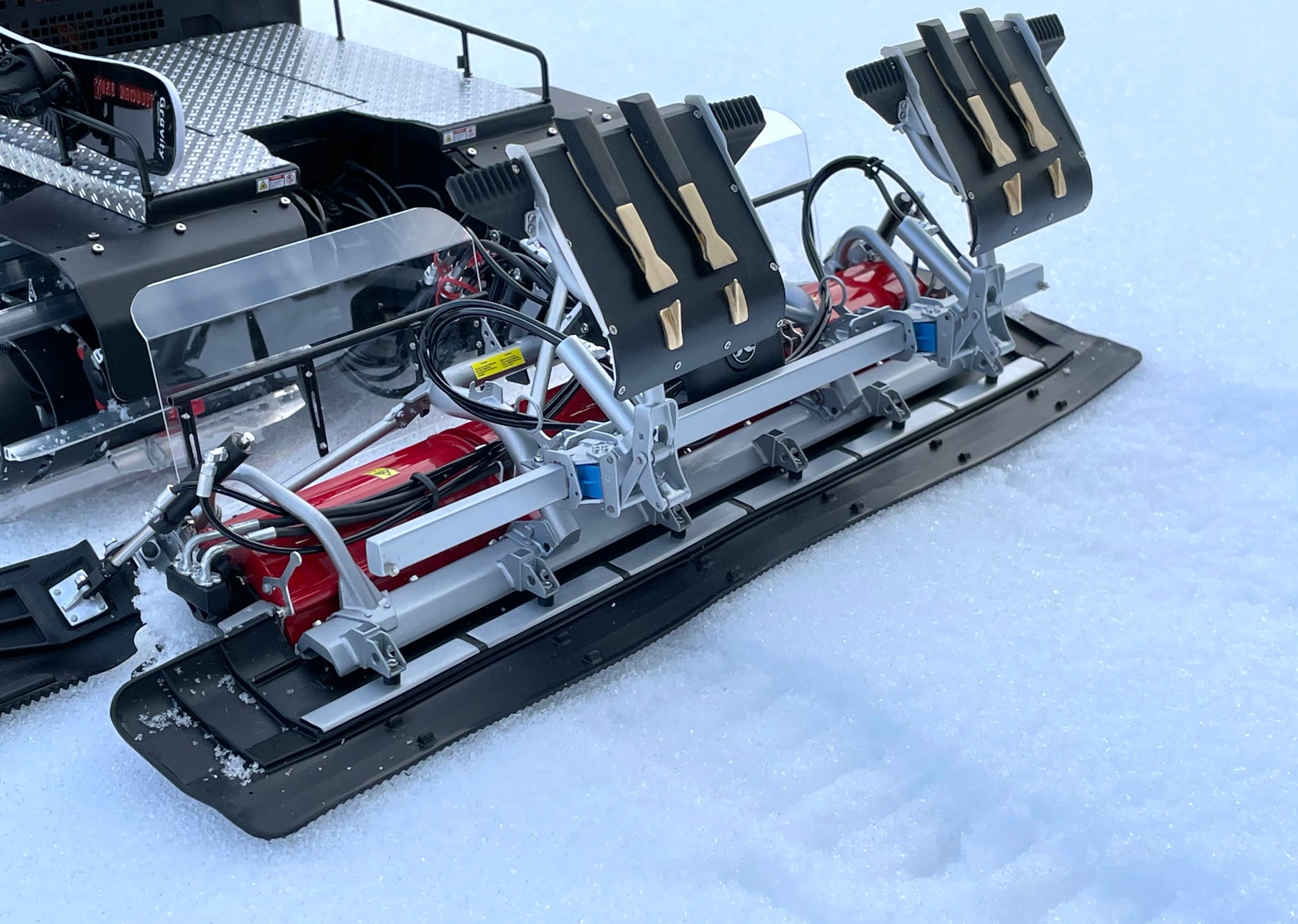
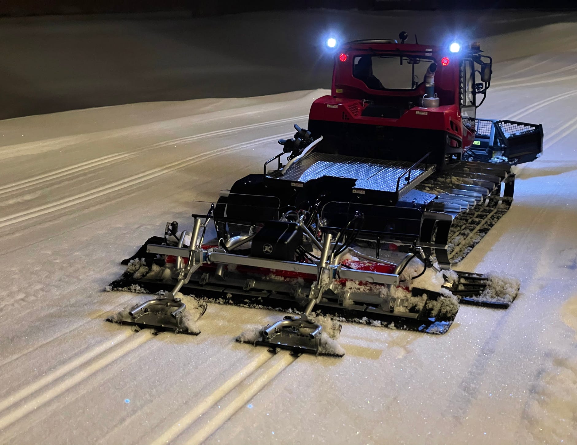
Track setter with two setting plates
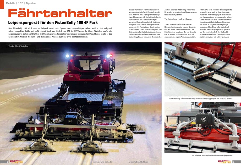
The original PB100 will be mostly seen grooming cross country tracks. Although I built a PB100 Park this characteristic attachment may not be missing. And who says that it can occasionally be used for track setting as well?
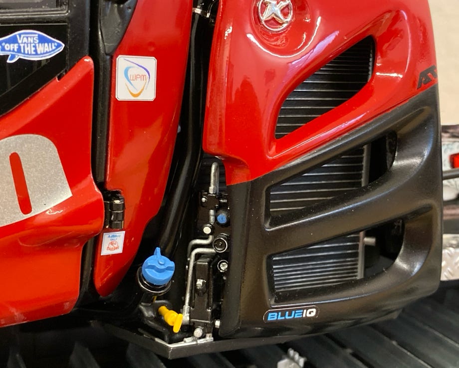
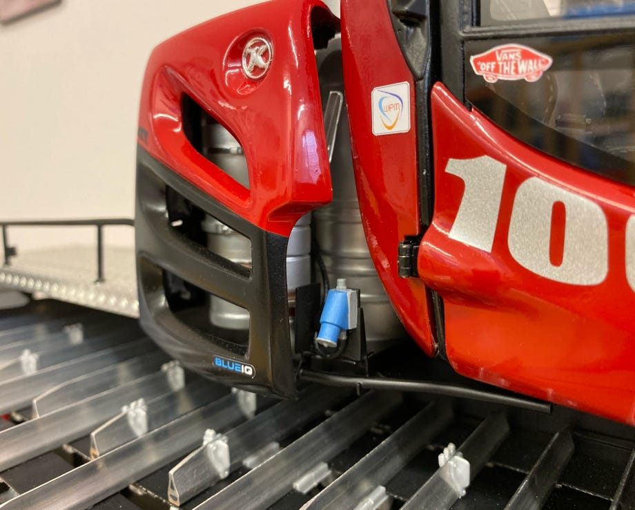
Kindly Kässbohrer provided drawings which helped me to design the attachment in true scale in CAD. Of course the track setters will be lifted hydraulically, and I already provided everything at the snow cat. ScaleArt offers miniature quick couplers. With them I can install the track setter quickly if needed. If they’re not used I store them under the hood where they’re held in position by a magnet (see pictures below).
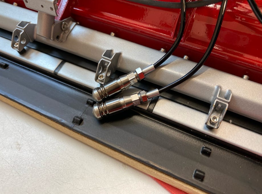
Hydraulic quick connectors by ScaleArt
Here they are stored under the hood.
The individual parts are as usual mostly printed brass parts. I put greatest emphasis on being true to the original. For the setting plates I used tiny M1 screws. The small finishers at the setting plates were printed with elastomeric polyurethane, a brand new although rather expensive material which is just like rubber.
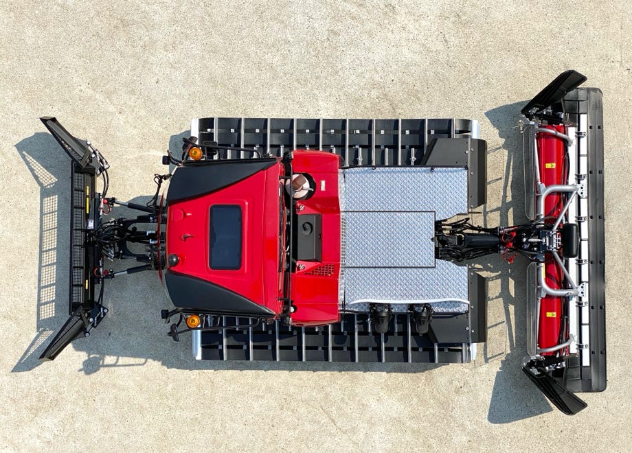
Here are a few pictures in comparison with the original:

Track setter at the model…
… and at the original (Photo: Adrian Humbel)
Lifting mechanism at the model…
… and at the original (Photo: Philipp Steinbacher)
If there are the right snow conditions it’s possible to create a perfect cross country skiing track even in scale 1:12. As far as I know these are the first model track setters world wide. At least I’m not aware of any others.
Here I want to thank everybody who helped me with this project:
General:
- Scale: 1:12
- Chassis tub, body, attachment carriers, blade, tiller are all self made
- Tracks and wheel suspension by Pistenking
- Gross weight: 4,4 kg (including battery, without track setter)
RC Functions:
- Speed
- Steering
- Windshield wipers
- Blade raise / lower (hydraulic)
- Blade tilt (hydraulic)
- Blade roll (hydraulic)
- Blade swivel (hydraulic)
- Blade wing right (hydraulic)
- Blade wing left (hydraulic)
- Tiller raise / lower (hydraulic)
- Tiller side finishers raise / lower (hydraulic)
- Tiller track setter raise / lower (hydraulic)
- Hydraulic pump speed
- Tiller wheel on/off
- Lights by Kingbus
- Temperature of the hydraulic oil by telemetry
Hydraulic Components:
- Motor-Pump-Unit by Modellbau Martin Kampshoff, Robbe brushless motor with Robbe speed controller
- Valves: 6x-valve block, 2x-valve block, single valve with integrated floating position for tiller by Modellbau Ulrich Meinhardt
- Hoses by Kampshoff and fittings by Leimbach, Kampshoff and ScaleArt
- Hydraulic cylinders: made by myself
- Operating pressure: 25 bar
Electronic Components:
- RC system ScaleArt Commander SA-1000 with CM-5000 receiver
- Double Speed Controller Pistenking
- Servos HiTec HS-65HB for valve blocks (9 pieces)
- Castle Creations CC BEC to supply the tiller wheel motors with 4,8 V
- Battery Turnigy nano-tech LiFePo 4S, 13.2 V, 20C discharge, 1600mAh
- Pistenking Kingbus Universal Modules for the lights
- Back-up warning beeper by Pistenking
- Rotating beacon by Pistenking modified to match Comet S
The german magazine Rad & Kette 1/2021, 2/2021 and 4/2021 issued an article in 3 parts by me about building the PB100 Park 4F. Part 1 deals with building the body and chassis, part 2 is about the accessories blade, tiller, and the hydraulics, and part 3 is about the track setter. They are in German language.
The articles can be downloaded as PDF file, with friendly permission by the magazine. Just click on the picture for downloading.
Diese Seite verwendet Cookies. Sie stimmen der Verwendung von Cookies durch Anklicken von “OK” zu. Nähere Informationen finden Sie in unseren Datenschutzbestimmungen.
This page is using Cookies. You are permitting the use of cookies by clicking on “OK”. More information can be found at our Privacy Protection.
OK


